
Electronic device for performing antenna tuning and method therefor

a technology of electronic devices and antennas, applied in the direction of electrical equipment, transmitter monitoring, transmission monitoring, etc., can solve the problems of gradually scarce frequency resources, and achieve the effect of high wireless signal quality

Pending Publication Date: 2021-12-16
SAMSUNG ELECTRONICS CO LTD
View PDF2 Cites 0 Cited by
  • Summary
  • Abstract
  • Description
  • Claims
  • Application Information

AI Technical Summary

Benefits of technology

The patent describes a way to improve wireless signal quality on electronic devices by using a reflective wave to tune the antenna. This helps to maintain high signal quality without being limited by the frequency range. The technical effect is better wireless communication.

Problems solved by technology

Frequency resources have become gradually scarce due to the widespread use of various wireless services, but users of wireless services still want high-quality services having the high throughput and low latency.

Method used


Image

  • Electronic device for performing antenna tuning and method therefor
  • Electronic device for performing antenna tuning and method therefor
  • Electronic device for performing antenna tuning and method therefor

Examples


Embodiment Construction

Technical Problem

[0004]Several events that affect performance of an antenna may be experimentally identified in advance, and adjustment values of antenna parameters for overcoming the events may be identified. Based on the description above, I / Q values of a reflective wave, which have errors due to several events, may be identified in advance, and accordingly, parameters for optimizing an antenna may be stored.

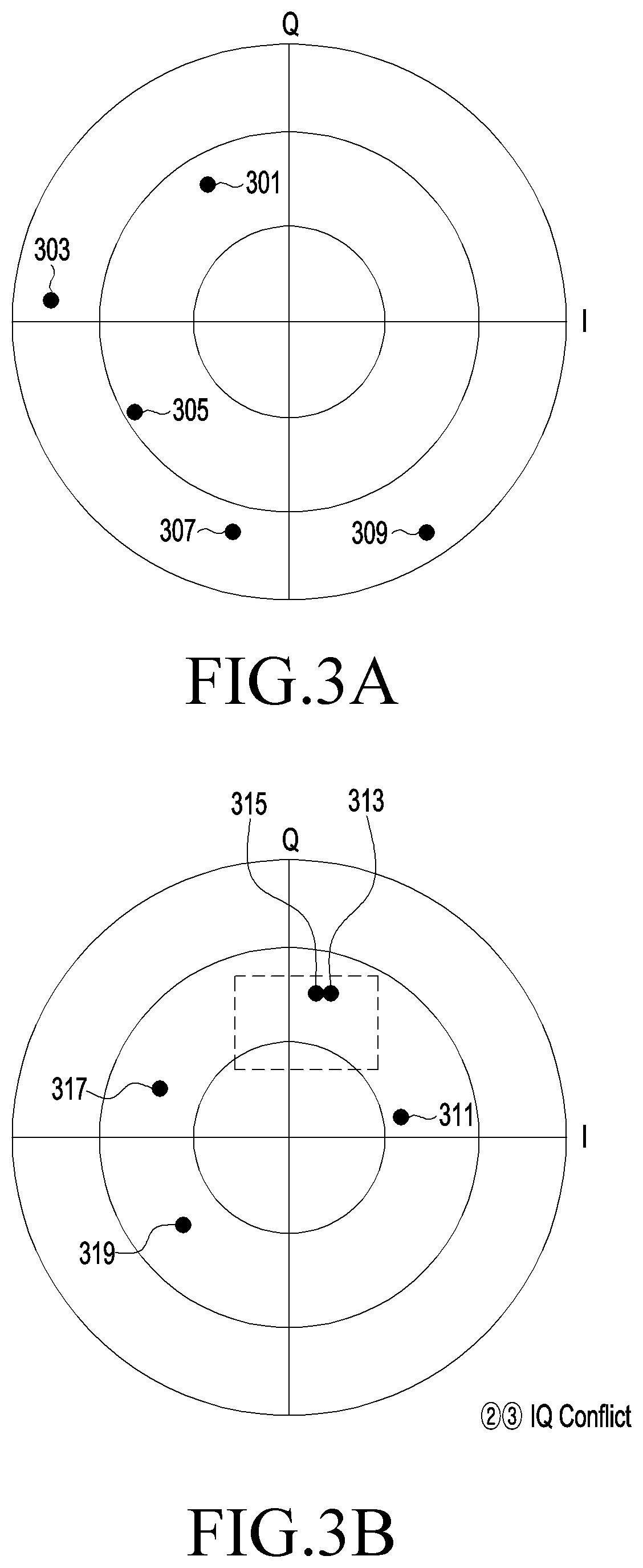
[0005]However, as an amount of change in the I / Q values becomes small at a high frequency, there may be a case where I / Q values of a reflective wave, which have errors due to several events, overlap each other, and in this case, it may be difficult to identify an event which has caused an error. For example, if an I / Q value of a reflective wave, which has an error caused by a user's antenna grip, and an I / Q value of a reflective wave, which has an error caused by an earjack connection, overlap each other, it may be difficult to identify whether the error is an error caused by ...


PUM


Abstract

According to various embodiments, an electronic device may comprise: a housing; a wireless communication circuit positioned inside the housing so as to transmit / receive at least one radio frequency (RF) signal; multiple antennas positioned inside the housing or configured as parts of the housing and electrically connected to the wireless communication circuit; at least one processor operably connected to the wireless communication circuit; and a memory operably connected to the at least one processor. The memory may store a lookup table comprising a first set of antenna modes regarding at least some of the multiple antennas and a second set of antenna modes regarding at least some of the multiple antennas. In addition, the memory may store instructions that, when executed, cause the processor to: cause the wireless communication circuit to transmit a signal in a first antenna mode included in the first set; cause the wireless communication circuit to receive a reflective wave of the transmitted signal; acquire a measurement value of the received reflective wave; confirm whether or not the measurement value is included within at least one designated range; confirm a second antenna mode corresponding to the acquired measurement value, among the antenna modes included in the second set, if it is confirmed that the measurement value is included in at least one designated value; and cause the wireless communication circuit to transmit the signal in the second antenna mode. Other various embodiments are possible.

Description

TECHNICAL FIELD[0001]Various embodiments relate to an electronic device for performing antenna tuning, based on a reflective wave of a transmission signal, and a method therefor.BACKGROUND ART[0002]Frequency resources have become gradually scarce due to the widespread use of various wireless services, but users of wireless services still want high-quality services having the high throughput and low latency. Accordingly, a broadband wireless system in a high frequency band has been developed in order to provide a new wireless service (for example, a fifth generation (5G) cellular system).[0003]Meanwhile, since performance of an antenna may be greatly affected by an external environment, tuning such as adjusting antenna parameters may be performed. When antenna tuning is performed, a method of performing tuning by receiving a reflective wave transmitted from a terminal and analyzing an impedance thereof may be used.DETAILED DESCRIPTION OF THE INVENTIONTechnical Problem[0004]Several ev...

Claims


Application Information

Patent Timeline
Patent Type & Authority Applications(United States)
IPC IPC(8): H04B17/12H01Q1/24H04B17/10
CPCH04B17/12H04B7/0413H04B17/103H01Q1/24H04B7/0689
Inventor LEE, YOUNGKWONYU, HYUNGJOONCHA, SONGSUB
Owner SAMSUNG ELECTRONICS CO LTD
Learn More