Connection of cup and paint sprayer

a technology of sprayer and cup, which is applied in the direction of sleeves/socket joints, pipe joints, couplings, etc., can solve the problem of taking a lot of tim

Inactive Publication Date: 2006-05-02
HSIANG SHIN KUEI
View PDF9 Cites 87 Cited by
  • Summary
  • Abstract
  • Description
  • Claims
  • Application Information

AI Technical Summary

Problems solved by technology

This takes a lot of time.

Method used


Image

  • Connection of cup and paint sprayer
  • Connection of cup and paint sprayer
  • Connection of cup and paint sprayer

Examples


Embodiment Construction

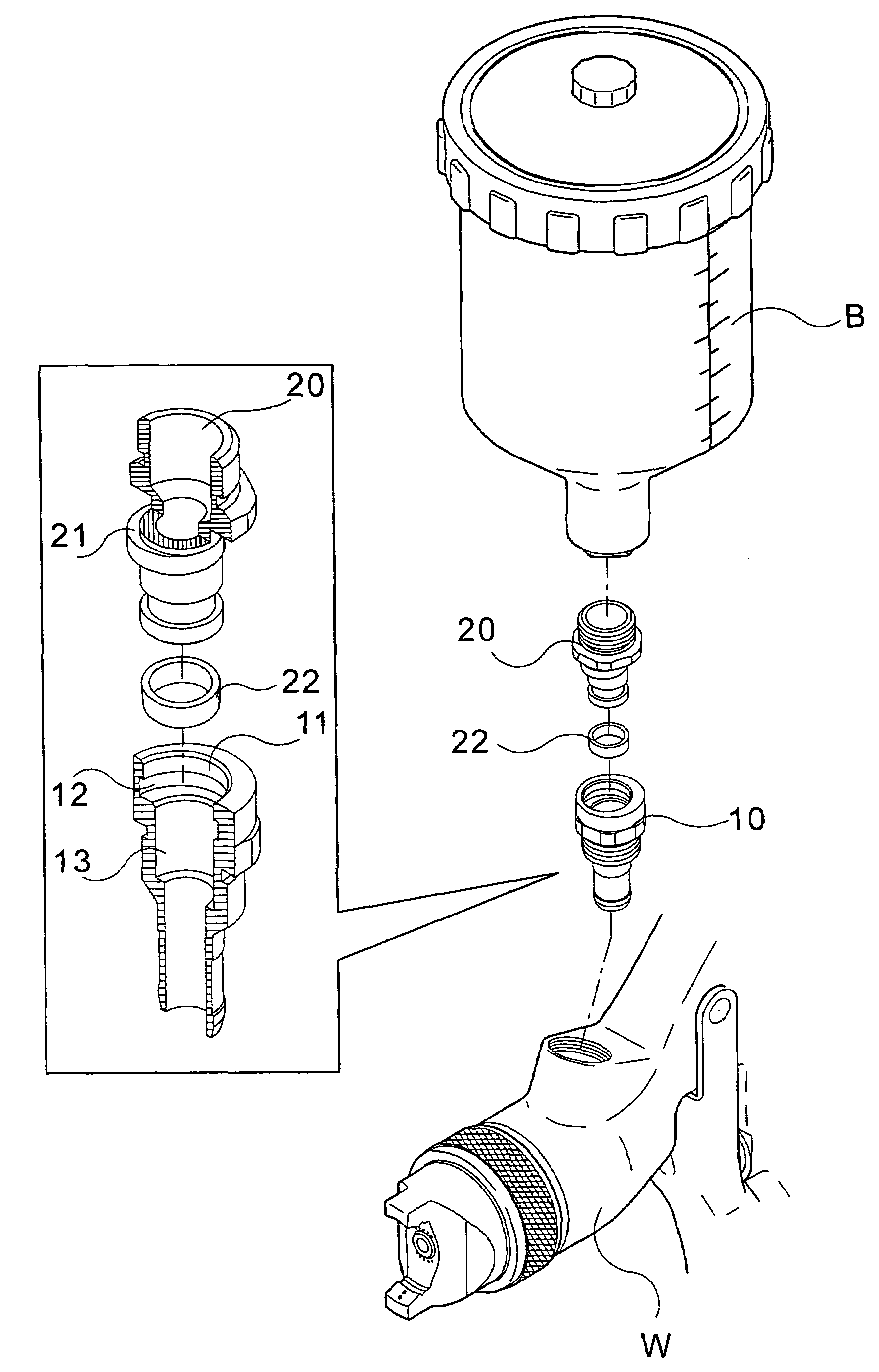
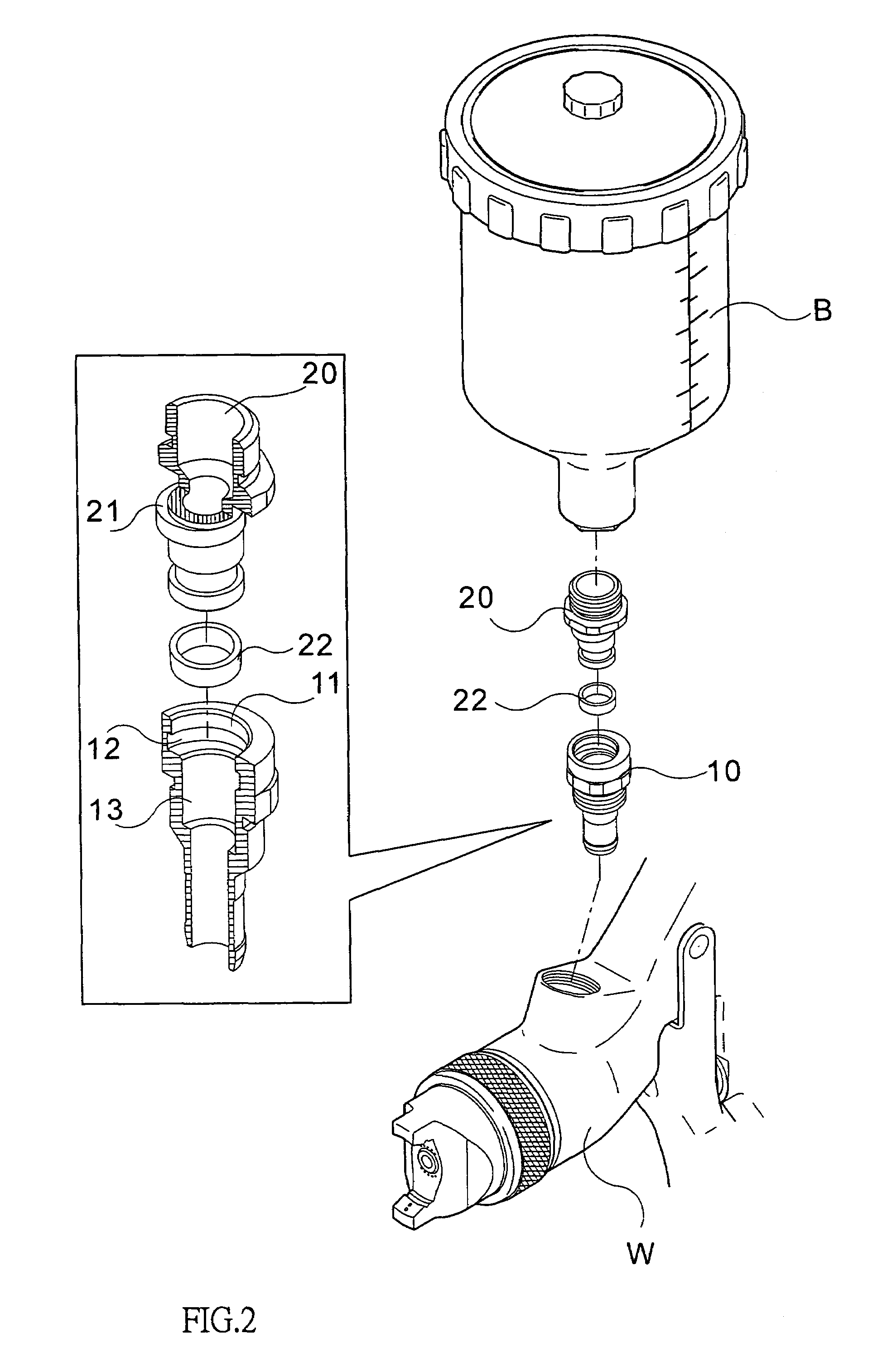
[0011]Referring to FIGS. 2 to 3, the paint sprayer “W” of the present invention comprises a threaded hole defined in a barrel of the sprayer “W” and a connection member 10 is threadedly engaged with the threaded hole in the sprayer “W”. The connection member 10 has a passage 13 defined therethrough and shares a common axis with the threaded hole in the sprayer “W”. An eccentric hole 11 is defined in a top of the connection member 10 and an annular groove 12 is defined in an inner periphery of the eccentric hole 11. An inner diameter of the annular groove 12 is larger than an inner diameter of the eccentric hole 11.

[0012]An insertion piece 20 has a first end fixed to a cup “B” and a flange 21 eccentrically extends outward from an outer periphery of the insertion piece 20. A second end of the insertion piece 20 includes a groove with which a seal 22 is engaged. The second end of the insertion piece 20 is rotatably inserted in the connection member 10 via the eccentric hole 11 and the ...


PUM


Abstract

A paint sprayer includes a threaded hole defined in a barrel thereof and a connection member is threadedly engaged with the threaded hole. A passage defined through the connection member and shares a common axis with the threaded hole in the sprayer. An eccentric hole is defined in a top of the connection member and an annular groove is defined in an inner periphery of the eccentric hole. An inner diameter of the annular groove is larger than an inner diameter of the eccentric hole. An insertion piece has a first end fixed to a cup and a flange eccentrically extends outward from an outer periphery of the insertion piece. A second end of the insertion piece is rotatably inserted in the connection member via the eccentric hole and the flange is rotatably engaged with the annular groove. The cup can be quickly disengaged from or connected to the sprayer by rotating the cup less than one revolution.

Description

FIELD OF THE INVENTION[0001]The present invention relates to a paint sprayer and more particularly, to a connection of the cup and the sprayer. The cup can be quickly removed from or connected to the sprayer.BACKGROUND OF THE INVENTION[0002]A conventional paint sprayer is disclosed in FIG. 1 and generally includes a barrel with a handle connected to the barrel and pressurized air is provided into the barrel from a lower end of the handle. A cup is threadedly connected to a top of the barrel so that when the cup is disengaged from or connected to the barrel, the user has to rotate the cup several revolutions. This takes a lot of time.[0003]The present invention intends to provide a connection between the cup and the barrel of the sprayer wherein the cup can be disengaged from or connected to the sprayer by rotating the cup less than one revolution.SUMMARY OF THE INVENTION[0004]The present invention relates to a paint sprayer which comprises a threaded hole defined in a barrel of the ...

Claims


Application Information

Patent Timeline
Patent Type & Authority Patents(United States)
IPC IPC(8): B05B9/00B05B1/28B05B7/30F16L21/00F16L55/00
CPCB05B7/2408F16L37/103B05B7/2478Y10S239/14
Inventor HSIANG, SHIN KUEI
Owner HSIANG SHIN KUEI
Why Eureka
Try Eureka