Valve apparatus for air tool

a valve apparatus and air tool technology, applied in the direction of manufacturing tools, portable power-driven tools, drilling machines, etc., can solve the problems of difficult axial length reduction of valves, and the inability of conventional valve apparatuses for air tools to permit use of common bodies, so as to reduce the manufacturing cost of dies

Active Publication Date: 2006-05-02
SHINANO SEISAKUSHO
View PDF6 Cites 14 Cited by
  • Summary
  • Abstract
  • Description
  • Claims
  • Application Information

AI Technical Summary

Benefits of technology

[0007]In view of the above-described problem of the conventional valve apparatus for an air tool, an object of the present invention is to provide a valve apparatus for an air tool which enables compatible attachment of a reverse valve and a regulator valve to a body, thereby enabling common use of the same body between, for example, an air driver and an air sander.
[0010]The valve apparatus of the present invention enables common use of the same body between reversible-type air tools and regulator-type air tools, to thereby reduce manufacturing cost of dies for the body.

Problems solved by technology

In such a valve apparatus for an air tool in which a lever is screwed to the valve, reducing the width (axial length) of the valve is difficult, because a threaded hole must be formed in the valve.
However, because of its structure, the above-described conventional valve apparatus for an air tool cannot permit use of a common body between an air driver including a reverse valve and an air sander including a regulator valve.

Method used


Image

  • Valve apparatus for air tool
  • Valve apparatus for air tool
  • Valve apparatus for air tool

Examples


Embodiment Construction

[0014]An embodiment of the present invention will be described with reference to the drawings.

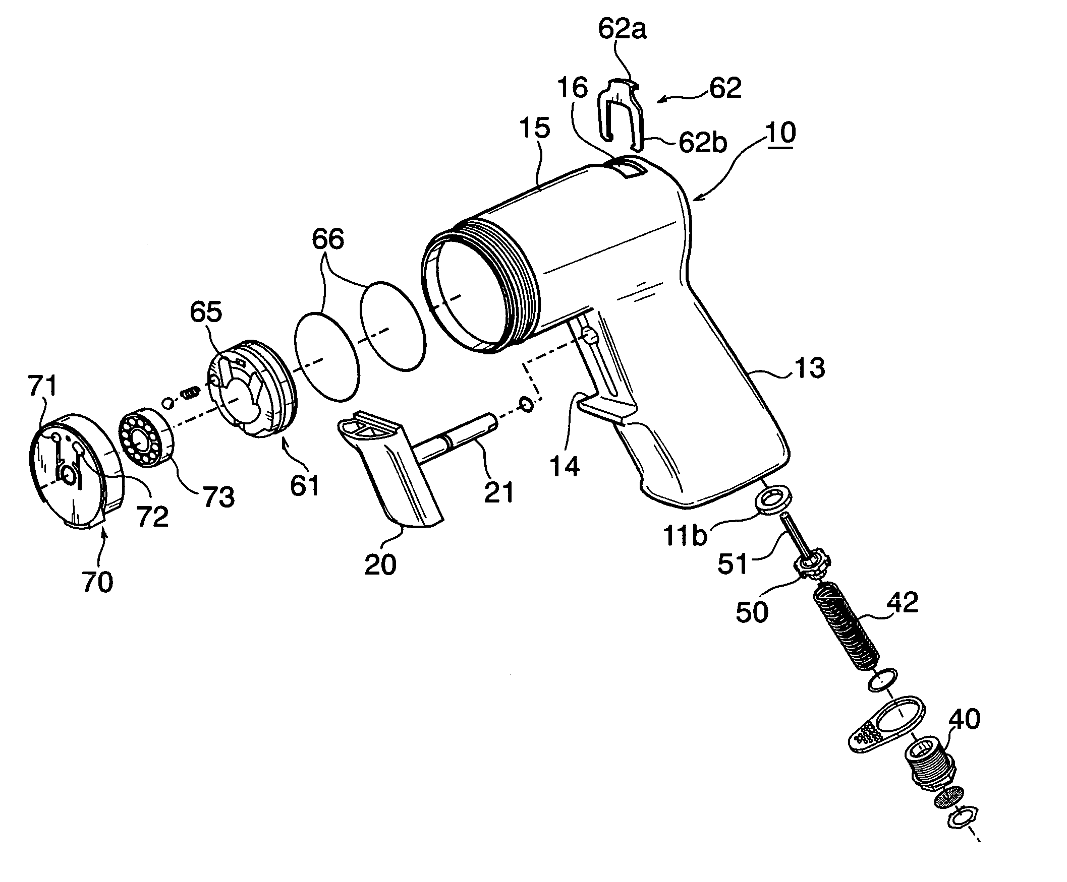
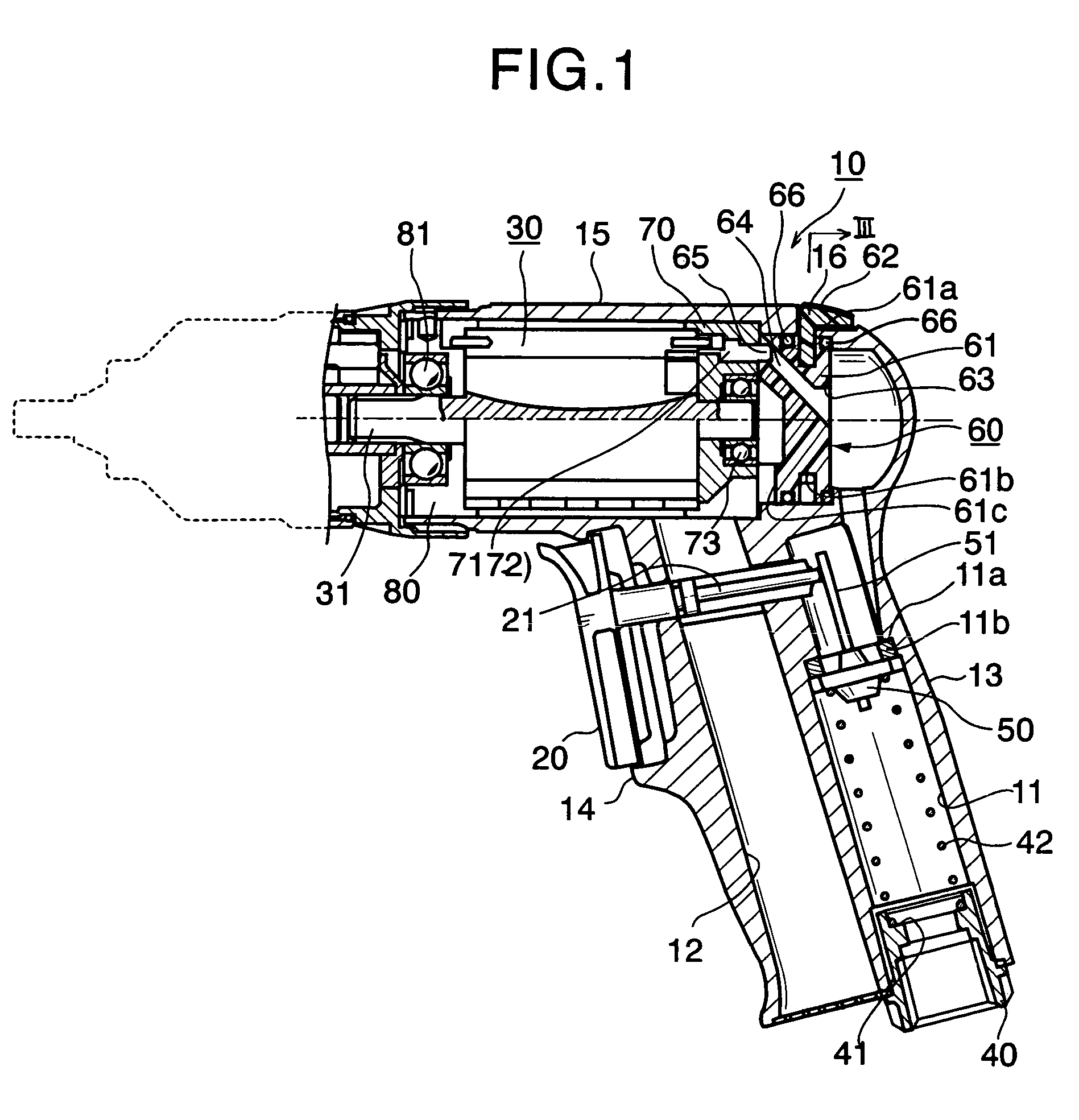
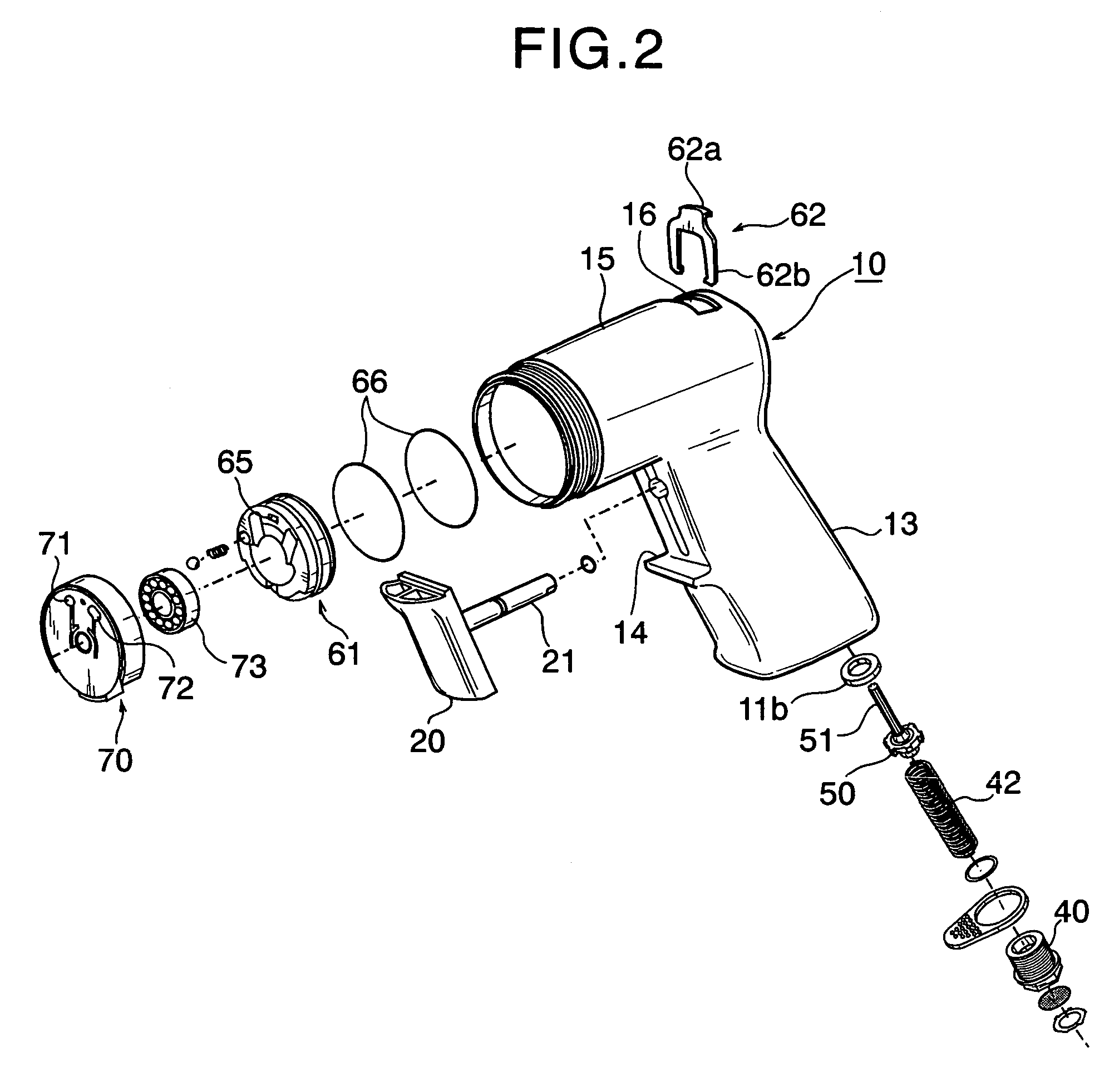
[0015]In FIG. 1, reference numeral 10 denotes a body of an air tool. The body 10 includes a grip portion 13 which has an air supply passage 11 and an air exhaust passage 12 formed therein; a trigger portion 14 which is formed above the grip portion 13 and supports a trigger 20; and a cylinder portion 15 which is formed above the trigger portion 14 and accommodates an air motor 30 therein.

[0016]A bushing 40 is fitted into the lower end of the air supply passage 11. A step 11a is formed at a middle portion of the air supply passage 11. A trigger valve 50 is seated on the step 11a via a valve seat 11b.

[0017]A valve spring 42 is disposed between the trigger valve 50 and a receiving portion 41 which is formed in an upper portion of the bushing 40. Thus, the trigger valve 50 is pushed against the valve seat 11b by means of the valve spring 42.

[0018]A pin 51 is affixed to the trigger valve 50, an...


PUM

PropertyMeasurementUnit
widthaaaaaaaaaa
axial lengthaaaaaaaaaa
rotationaaaaaaaaaa

Abstract

A valve apparatus for an air tool which has a valve rotatably disposed in a cylinder portion of a body of the air tool in which an air motor is accommodated; and a lever fixed to the valve and slidably received within a slit-shaped opening formed in the cylinder portion. The valve includes a first disc portion having an air inlet, a lever-fixing portion having an air passage which communicates with the air inlet, and a second disc portion having an air outlet which communicates with the air passage. The lever-fixing portion is narrower than the first and second disc portions. The lever has a knob portion slidable within the opening and a generally U-shaped engagement portion fixed to the lever-fixing portion so that two legs of the engagement portion sandwich the lever-fixing portion from diametrically opposite sides.

Description

BACKGROUND OF THE INVENTION[0001]1. Field of the Invention[0002]The present invention relates to a valve apparatus for an air tool, and more particularly to a valve apparatus suitable for air drivers, air drills, air sanders, and the like.[0003]2. Description of the Related Art[0004]As in the case of a ⅜″ reversible air drill (model number: CP-789R-26) of Chicago Pneumatic (see http: / / www.jackxchange.com / products / CP-789R-26.cfm), a conventional valve apparatus for an air tool includes a valve rotatably disposed in a cylinder portion of the body in which an air motor is accommodated, and a lever which is screwed to the valve and is supported to be slidable within a slit-shaped opening formed in the cylinder portion.[0005]In such a valve apparatus for an air tool in which a lever is screwed to the valve, reducing the width (axial length) of the valve is difficult, because a threaded hole must be formed in the valve. Air tools include those which require a reverse valve for changing th...

Claims


Application Information

Patent Timeline
Patent Type & Authority Patents(United States)
IPC IPC(8): F16K51/00B25B21/00B25F5/00F02B19/10
CPCB25F5/00
Inventor IZUMISAWA, NOBUYUKI
Owner SHINANO SEISAKUSHO
Why Eureka
Try Eureka