Position detecting device and position indicator thereof

a technology of position indicators and detecting devices, which is applied in the direction of instruments, computing, electric digital data processing, etc., can solve the problems of difficult to sufficiently lower the resistance value when it is turned, thick pen, and difficulty in reducing so as to reduce the resolution and accuracy of the calculation of the rotation angle. , the distance between the center of two magnetic cores is also shortened, and the distance between two coordinates detected by the tablet is also

Active Publication Date: 2018-08-16
WACOM CO LTD
View PDF12 Cites 16 Cited by
  • Summary
  • Abstract
  • Description
  • Claims
  • Application Information

AI Technical Summary

Benefits of technology

[0018]According to embodiments of the present invention, the plural electrodes are provided at the position indicating part (e.g., pen tip part) of the position indicator and the driven electrode(s) is switched time-wise serially. This allows for determining a rotation angle of the position indicator about the perpendicular direction to the tablet surface as well as a tilt of the position indicator relative to the tablet surface.
[0018]According to embodiments of the present invention, the plural electrodes are provided at the position indicating part (e.g., pen tip part) of the position indicator and the driven electrode(s) is switched time-wise serially. This allows for determining a rotation angle of the position indicator about the perpendicular direction to the tablet surface as well as a tilt of the position indicator relative to the tablet surface.
[0020]According to embodiments of the present invention, a magnetic material such as a ferrite core does not need to be used for the position indicator. Therefore, even when the position indicator, whose rotation angle and tilt can be obtained, is formed into a thin shape, the position indicator is not easily broken due to shock from, e.g., being dropped.
[0021]According to embodiments of the present invention, a coordinate position is obtained by electrostatic coupling with the tablet. Therefore, the tablet sensor can be used commonly as the sensor for a touch panel of the electrostatic system, while at the same time achieving a position indicator whose rotation angle and tilt can be obtained.

Problems solved by technology

The pen-shaped position indicator of the above-described Patent Document 1 has a problem that the pen is thick because two magnetic cores are juxtaposed at the tip part.
This lowers the resolution and accuracy in calculation of a rotation angle.
This analog switch is configured by a semiconductor circuit and therefore it is difficult to sufficiently lower the resistance value when it is turned on.
Accordingly, it is difficult to sufficiently suppress magnetic flux passing through the magnetic core surrounded by the control coil.
A second problem in thinning the magnetic cores is that shock due to, e.g., dropping of the pen breaks the core more easily.
Another problem (third problem) of the position detecting device described in Patent Document 1 is that integration with (finger) touch detection is difficult.
However, in contrast to a tablet of the electrostatic induction system, which uses a sensor obtained by arranging electrodes along the X direction and the Y direction, the tablet of the electromagnetic induction system of Patent Document 1 needs to have a sensor obtained by arranging loop coils and therefore it is difficult to provide the tablet sensor as a sensor compatible with both multi-touch input and pen input.

Method used


Image

  • Position detecting device and position indicator thereof
  • Position detecting device and position indicator thereof
  • Position detecting device and position indicator thereof

Examples


first embodiment example

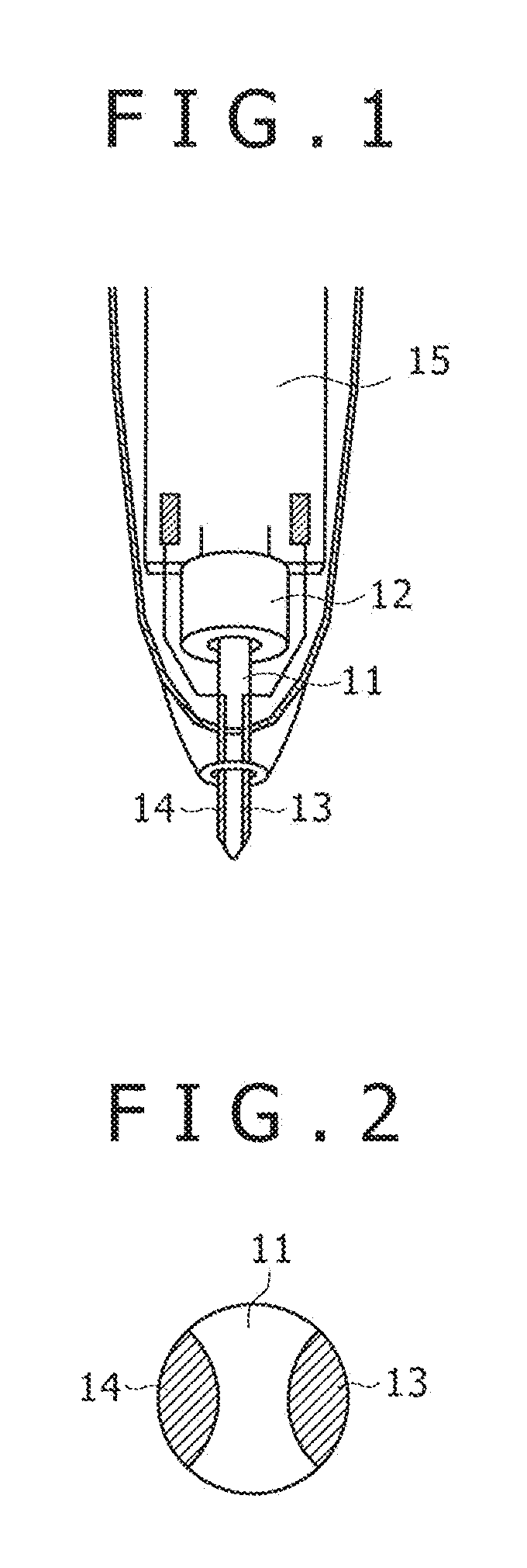
[0044]FIG. 1 is a diagram showing the structure of a position indicating part in a position indicator of a first embodiment example according to the present invention. In FIG. 1, numeral 11 denotes a core that transmits pressure applied to the pen tip and it is molded by an insulating material such as plastic. Numeral 12 denotes a variable-capacitance capacitor whose capacitance changes depending on the writing pressure applied via the core 11 and, e.g., such as the one disclosed in Japanese Patent Laid-open No. Hei 4-96212 (Patent Document 2). The variable-capacitance capacitor 12 has a coupling part to the core 11 as disclosed in the above-described Patent Document 2 and this coupling part is so configured as to slightly move together with the core 11 depending on the writing pressure applied to the core 11.

[0045]Numerals 13 and 14 denote electrodes and they are buried in the core 11. FIG. 2 is a sectional view when the core 11, in which the electrodes 13 and 14 are buried, is cut...

second embodiment example

[0109]FIG. 10 is a diagram showing the structure of a position indicating part in a position indicator of a second embodiment example according to the present invention. In FIG. 10, the same part as that in FIG. 1 is given the same reference numeral. That is, numeral 12 denotes a variable-capacitance capacitor whose capacitance changes depending on the writing pressure and numeral 15 denotes a printed board. A core 35 is coupled to the variable-capacitance capacitor 12 and the writing pressure applied to the tip of the core 35 is detected. Numeral 36 denotes a chassis and a hole through which the core 35 passes is made at its tip part.

[0110]Two electrodes 37 and 38 are provided at the tip part of the chassis 36 and FIG. 11 is a diagram showing the arrangement thereof. The following description will be so made that the electrodes 37 and 38 are called the L electrode and the R electrode, respectively.

[0111]FIG. 12 is a circuit configuration diagram of the position indicator of the sec...

third embodiment example

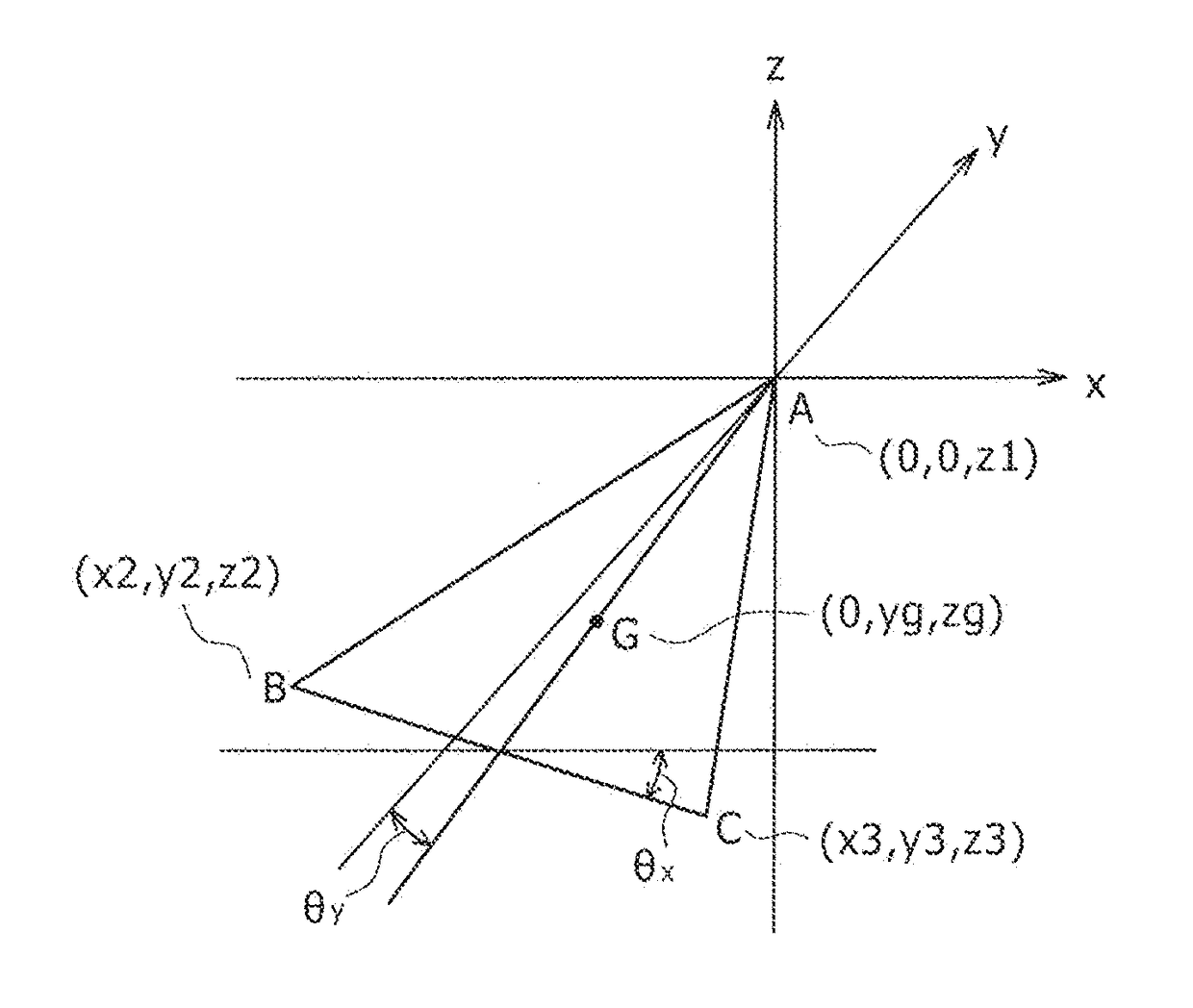
[0128]FIG. 15 is a diagram showing the structure of a position indicating part in a position indicator of a third embodiment example according to the present invention. In the present embodiment example, an example is shown in which three electrodes are disposed in the position indicator and a tilt of the position indicator relative to the tablet is obtained in addition to a rotation angle thereof.

[0129]In FIG. 15, the same part as that in FIG. 10 is given the same reference numeral. That is, numeral 12 denotes a variable-capacitance capacitor whose capacitance changes depending on the writing pressure. Numerals 15, 35, and 36 denote a printed board, a core, and a chassis, respectively.

[0130]Three electrodes 40, 41, and 42 are provided at the tip part of the chassis 36 and FIG. 16 is a diagram showing the arrangement thereof. These three electrodes are connected to the printed board 15 by a connection line (not shown).

[0131]FIG. 17 is a circuit configuration diagram of the position ...


PUM


Abstract

A method is disclosed to detect a tilt angle of a pen-shaped position indicator relative to a sensor surface of a tablet. The position indicator includes a first pen electrode and a second pen electrode. The sensor surface includes X electrodes and Y electrodes that intersect each other. The position indicator transmits a first signal from the first pen electrode and a second signal from the second pen electrode. The tablet detects a first signal intensity level V1 of the first signal based on a highest signal level Vpx1 detected in one of the X electrodes in response to the first signal, and detects a second signal intensity level V2 of the second signal based on a highest signal level Vpx2 detected in one of the X electrodes in response to the second signal. The tablet determines a tilt angle of the pen-shaped position indicator relative to the sensor surface based on a difference between the first signal intensity level V1 and the second signal intensity level V2.

Description

CROSS-REFERENCE TO RELATED APPLICATION[0001]The present application claims priority under 35 U.S.C. 119(a) to Japanese Patent Application No. 2012-176102, filed Aug. 8, 2012, which is incorporated by reference herein.BACKGROUNDTechnical Field[0002]The present invention relates to position detecting devices and position indicators thereof, and particularly to a position detecting device capable of detecting a tilt of a position indicator having a pen shape, and / or a rotation angle of the position indicator about an axis defined by the perpendicular direction to a tablet surface, and a position indicator thereof.Description of the Related Art[0003]As this type of device, a position detecting device of the electromagnetic induction system is disclosed in Patent Document 1 (Japanese Patent Laid-open No. Hei 8-30374). According to an embodiment example of Patent Document 1, two magnetic cores are juxtaposed at the tip portion of a position indicator having a pen shape, and a control coil...

Claims


Application Information

Patent Timeline
Patent Type & Authority Applications(United States)
IPC IPC(8): G06F3/0354G06F3/044
CPCG06F3/044G06F3/03545G06F2203/04104G06F3/0442G06F3/0446G06F3/0441
Inventor KATSURAHIRA, YUJI
Owner WACOM CO LTD
Why Eureka
Try Eureka