Electromagnetic switch for starter

a technology of electric switch and starter spring, which is applied in the direction of electromagnetic relay, electrical apparatus, and electromagnetical relay details, can solve the problems of likely interference of the return spring around the rod, and achieve the effect of improving the mountability and sliding of the return spring

Inactive Publication Date: 2006-05-02
DENSO CORP
View PDF13 Cites 34 Cited by
  • Summary
  • Abstract
  • Description
  • Claims
  • Application Information

AI Technical Summary

Benefits of technology

[0007]It is another object to provide an electromagnetic switch for a starter, which is capable of being automatically assembled and providing air-tightness.
[0008]It is further another object to provide

Problems solved by technology

However, the return spring is likely to be interfered around the

Method used


Image

  • Electromagnetic switch for starter
  • Electromagnetic switch for starter
  • Electromagnetic switch for starter

Examples


second embodiment

[0067](Second embodiment)

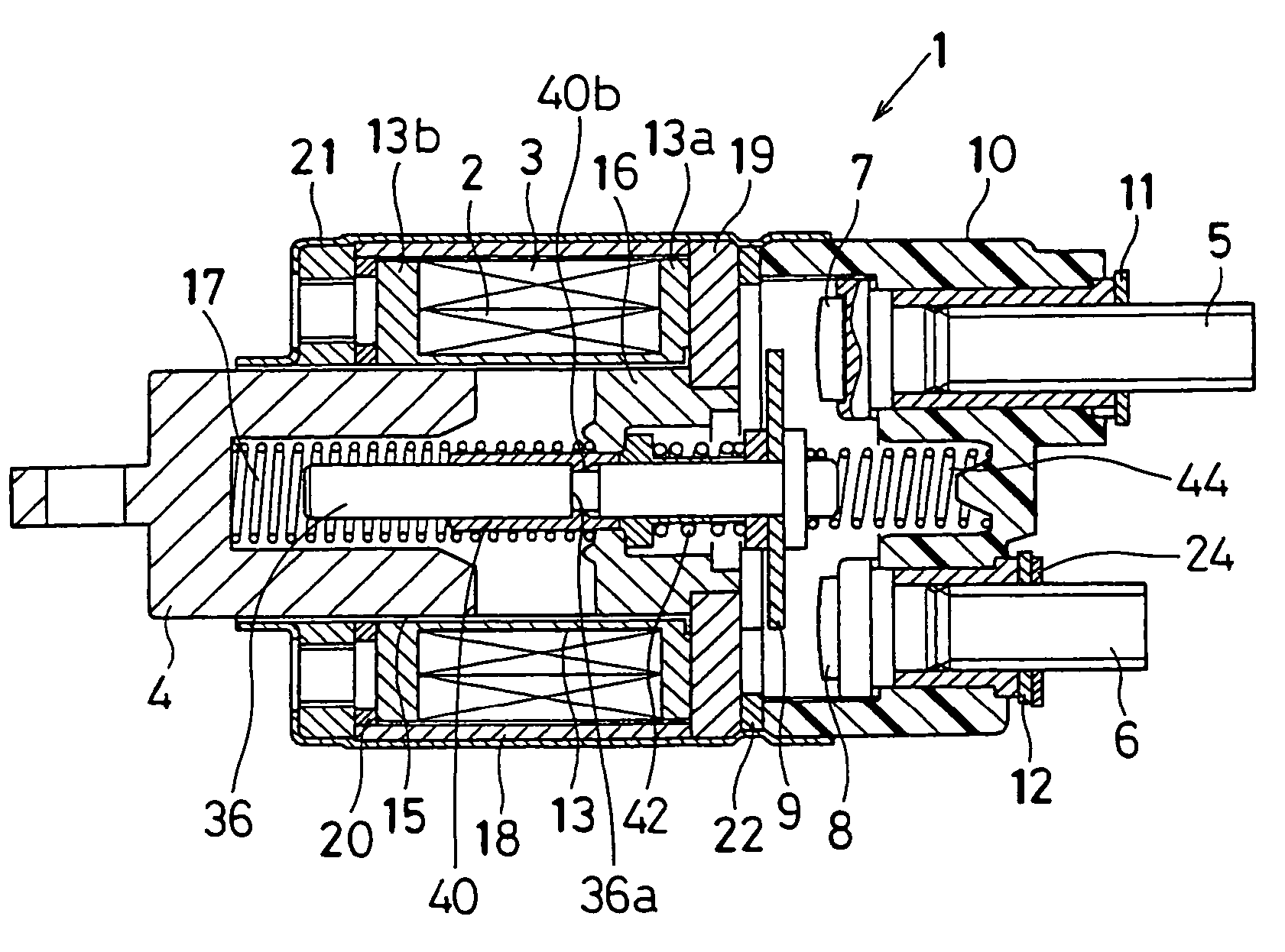
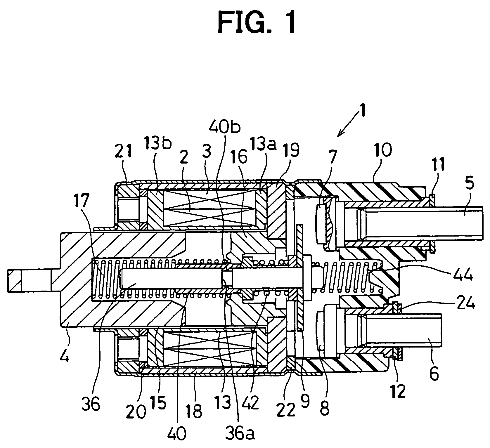
[0068]An axial length of the rod cover 40 may be increased as compared with that of the first embodiment. Preferably, an axial length L1 of the rod cover 40 from the distal end to the projections 40b is substantially equal to an axial length L2 of the rod 36 from a distal end to the annular groove 36a thereof, as shown in FIG. 13.

[0069]With this arrangement, an axial length of the slits 40c can be increased in the axial direction as compared with that of the first embodiment. Therefore, the cylindrical part 40s of the rod cover 40 can easily expand radially outward when it is mounted onto the rod 36. Accordingly, the pressing force required to mount the rod cover 40 onto the rod 36 can be decreased. Since the axial length of the slits 40c is increased, the cylindrical part 40s becomes flexible more than that of the first embodiment. Therefore, the deformation of the cylindrical part 40s can be decreased, and the return spring 17 is properly mounted onto the ...


PUM


Abstract

In an electromagnetic switch of a starter, a bobbin has two terminal holders on a flange. Each of the terminal holders defines a slot on its end surface and a terminal is press-fitted in the slot in an axial direction of the bobbin. An end of an excitation coil wound around the bobbin is pulled out the bobbin and connected to the terminal. A molded cover provides a through hole and is mounted on the terminal so that the terminal passes through the through hole. A sealing member is press-fitted on the terminal to air-tightly seal the through hole. A rod cover fitted on a rod supporting a movable contact has slits on its cylindrical part in the axial direction. The slits are closed before a distal end of the cylindrical part.

Description

[0001]This is a Division of application Ser. No. 10 / 103,730 filed Mar. 25, 2002 now U.S. Pat. No. 6,762,663. The entire disclosure of the prior application is hereby incorporated by reference herein in its entirety.CROSS REFERENCE TO RELATED APPLICATION[0002]This application is based on Japanese Patent Applications No. 2001-109102 filed on Apr. 6, 2001, and No. 2001-220299 filed on Jul. 19, 2001, the disclosure of which is incorporated herein by reference.FIELD OF THE INVENTION[0003]The present invention relates to an electromagnetic switch used in a starter for starting an internal combustion engine.BACKGROUND OF THE INVENTION[0004]According to an electromagnetic switch in JP-U-63-50432, a sealing member 120 is compressively fitted in a recess 110 formed on the inner wall of a molded cover 100, as shown in FIG. 10. A lead wire 140 of a coil is pulled out of the molded cover 100 through a through hole 130 of the molded cover 100 and a through hole in the sealing member 120. An end o...

Claims


Application Information

Patent Timeline
IPC IPC(8): H01H67/02H01H50/02H01H50/44H01H51/06
CPCH01H51/065H01H50/443H01H50/023
Inventor ANDOH, KAZUHIROWAKAHARA, YASUYUKIKATOH, MASAHIROUSAMI, SHINJIINOGUCHI, TETSUNORI
Owner DENSO CORP
Why Eureka
Try Eureka