Display device and driving circuit for displaying

a display device and driver circuit technology, applied in the field of panel-type display devices, can solve the problems of unpractical use of this type of technology and lower power consumption of the device, and achieve the effects of reducing the color count of the original image received from a higher-level device, reducing power consumption, and prolonging operation

Active Publication Date: 2006-05-02
RENESAS ELECTRONICS CORP
View PDF7 Cites 9 Cited by
  • Summary
  • Abstract
  • Description
  • Claims
  • Application Information

AI Technical Summary

Benefits of technology

[0005]The object of the present invention is to provide a display device and driver circuit for the same, in which the color count of an original image received from a higher-level device is reduced and the power consumption is limited based on this color count reduction, so that longer operation is possible.
[0006]The present invention allows images to be displayed using a plurality of color reduction rates and also allows color reduction rates to be selected externally through transfer of information from a higher-level device (e.g., a CPU), or by using manual setting means, such as a switch or jumper settings. To implement these features, a display device according to the present invention adds the following to a conventional display device: color reduction processing means for reducing the color count of gradation data in an original image based on color reduction rate data indicating a color reduction rate, and virtually representing the color count of the original image using the reduced color count; and means for partially stopping operations of the driver circuit based on the color reduction rate.
[0007]The present invention provides a display device and a display device driver circuit that controls display luminance based on applied voltages, wherein: color reduction rate data is received from the outside; the number of colors shown on the display is selected based on this color reduction rate data; and the operation of unnecessary driver circuits is stopped based on the number of displayed colors. As a result, the power consumed by the display device can be reduced. Also, it is possible to select between a high-quality mode with less color count reduction and a low-power mode with more color count reduction. As a result, a display device that is convenient to use can be provided.

Problems solved by technology

As a result, the power consumption of the device is lower than when the real color count is directly displayed.
Thus, the usage of this type of technology has not been considered practical.

Method used


Image

  • Display device and driving circuit for displaying
  • Display device and driving circuit for displaying
  • Display device and driving circuit for displaying

Examples


first embodiment

[0052]Various embodiments of the present invention will be described in detail with reference to the drawings. the present invention will be described initially with reference to FIG. 1 through FIG. 23.

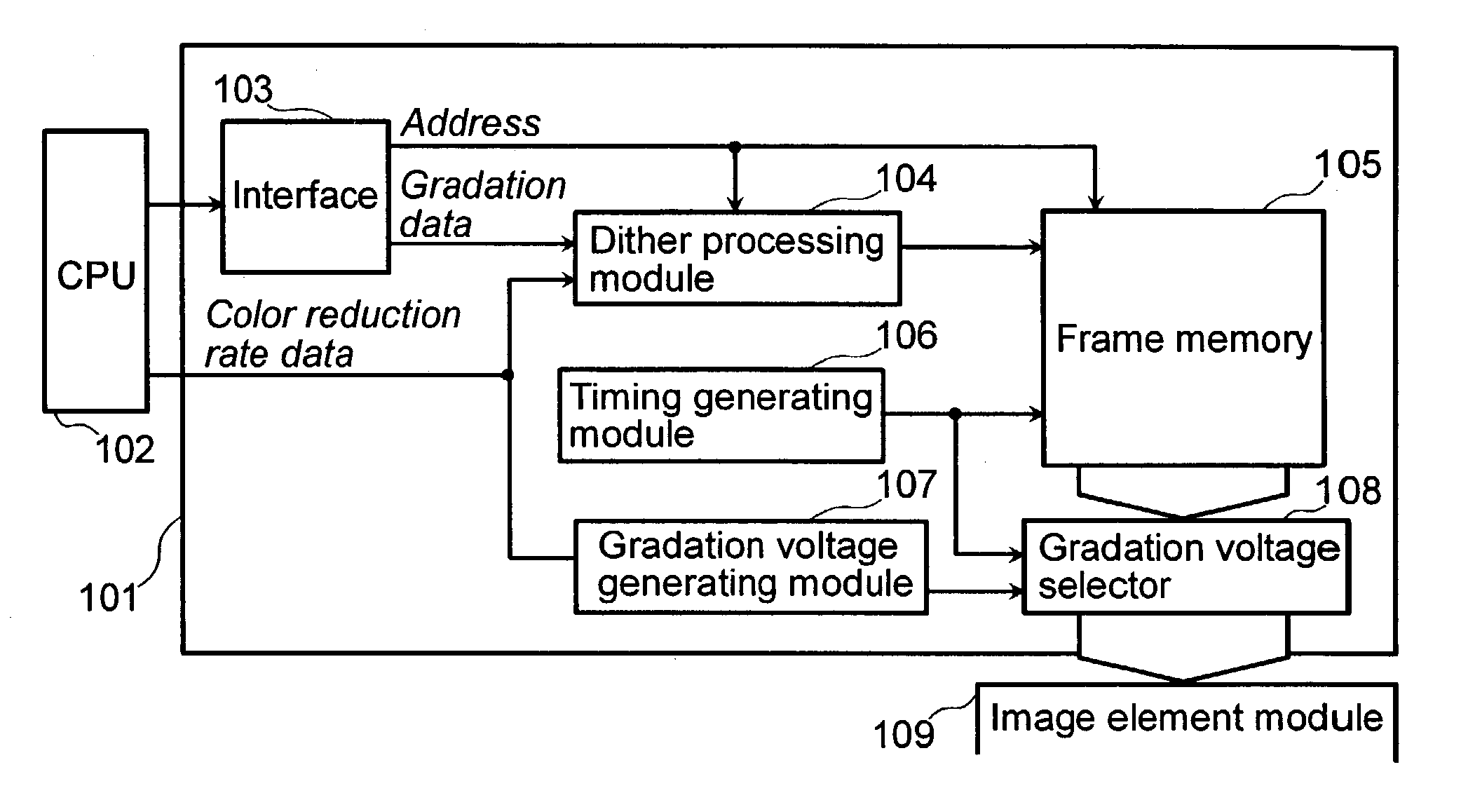
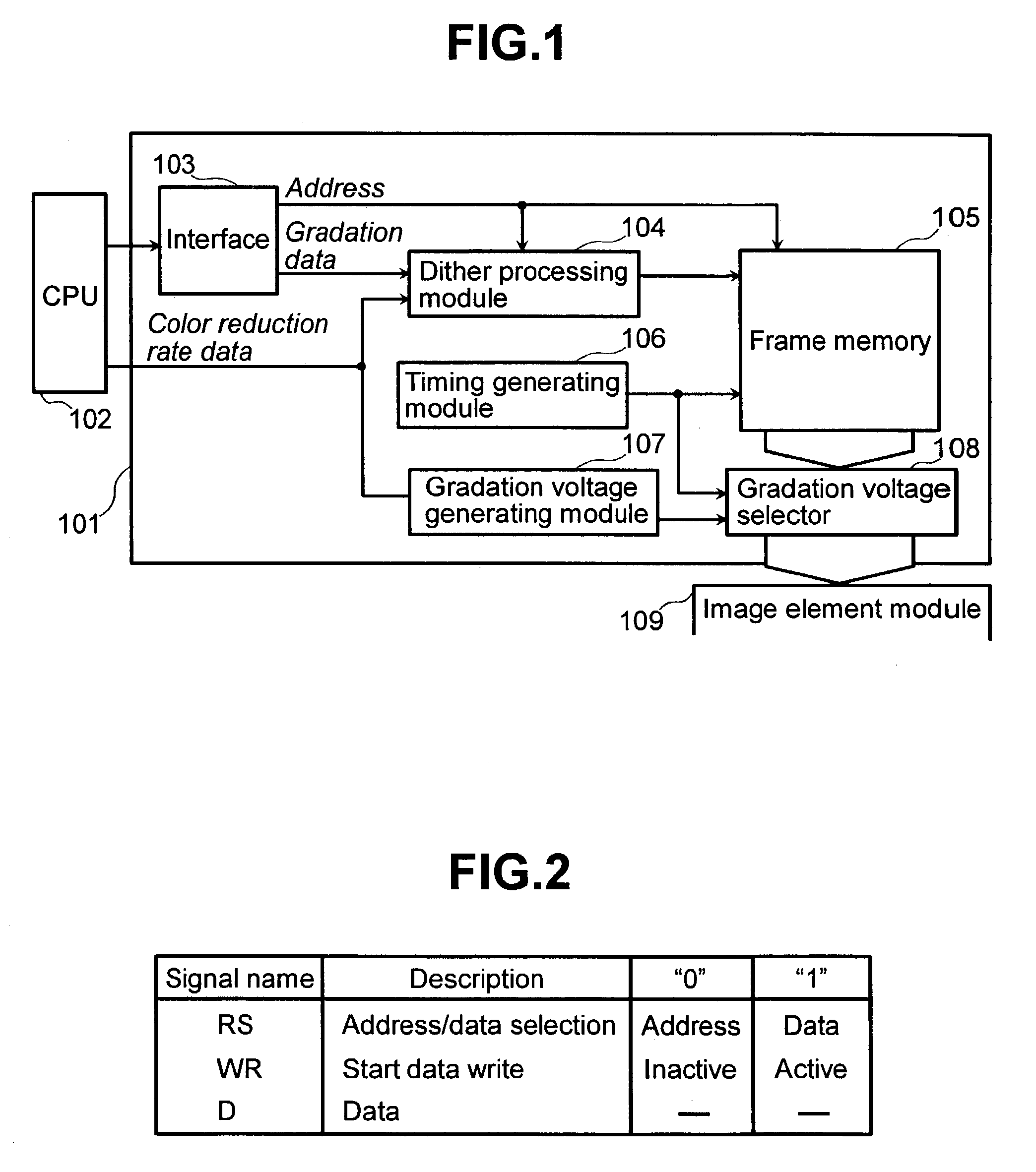
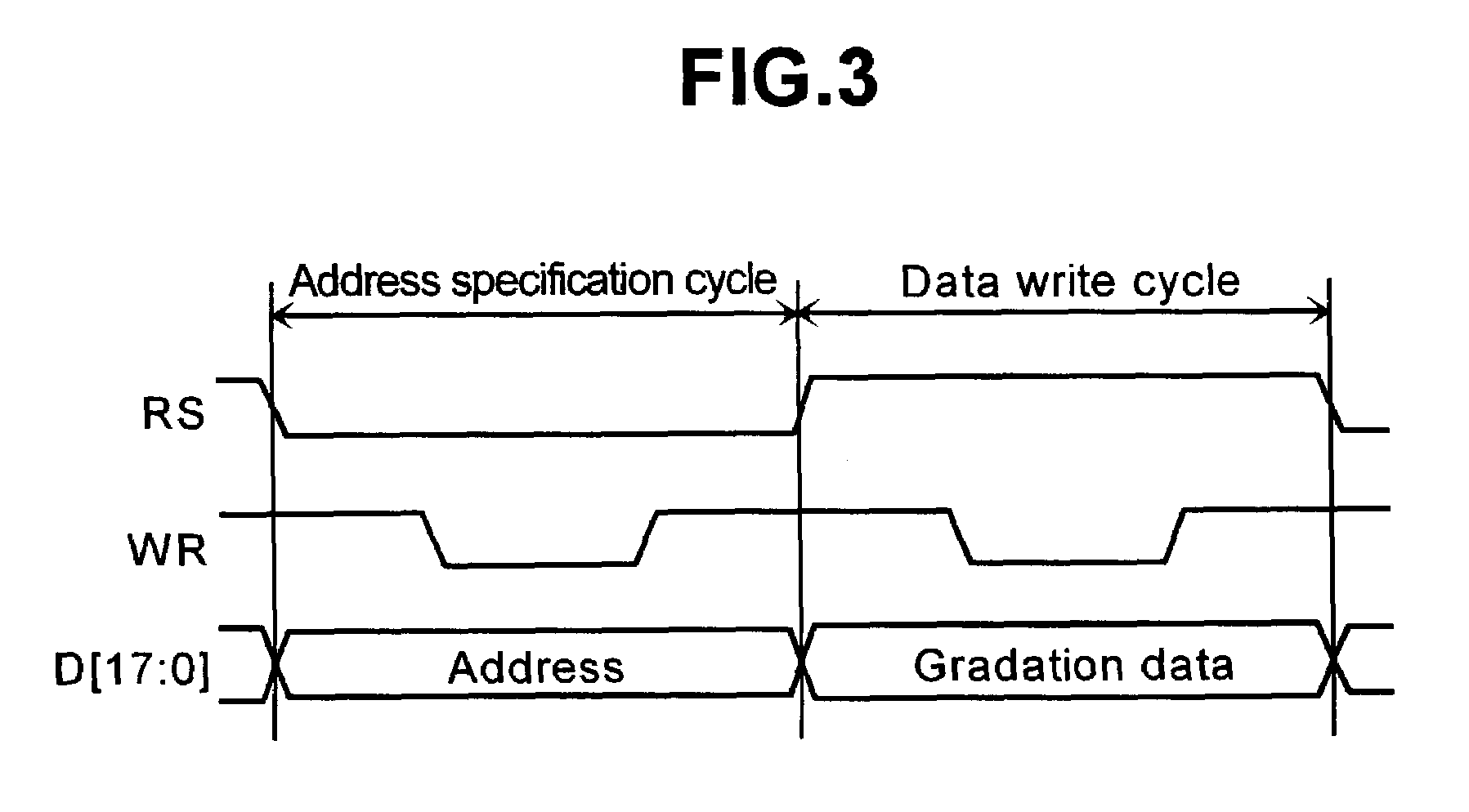
[0053]FIG. 1 is a block diagram of a display device driver circuit according to a first embodiment of a display device of the present invention. FIG. 1 shows: a data line driver 101; a CPU 102; an interface 103; a dither processing module 104; a frame memory 105; a timing generating module 106; a gradation voltage generating module 107; a gradation voltage selector; and an pixel module 109. FIG. 2 is a table showing interface input signals according to the first embodiment of the present invention. FIG. 3 is a timing chart illustrating the operations of the interface input signals according to the first embodiment of the present invention.

[0054]In this embodiment of the present invention, the pixel module 109 can be, for example, a TFT liquid crystal. A gradation voltage based on grad...

second embodiment

[0087]FIG. 34 is a block diagram showing the structure of a display device driver circuit according to the present invention. As shown in FIG. 34, it is possible to implement a display device driver circuit equipped with both dither processing and FRC processing. In this case, it would be possible to use just dither processing or FRC processing, or to use both in combination. This can be achieved by having the color reduction rate data provided separately for both dither processing and FRC processing. Furthermore, the present invention is not restricted to transferring color reduction data from the CPU, and it would also be possible to use jumper settings. Also, as shown in FIG. 35, it would be possible to select between CPU transfer and jumper settings.

[0088]Next, a third embodiment of the present invention will be described with reference to FIG. 36 through FIG. 41. In the first and the second embodiments of the present invention, display signals are transferred to the CPU, and th...


PUM

PropertyMeasurementUnit
voltagesaaaaaaaaaa
scan voltagesaaaaaaaaaa
sizeaaaaaaaaaa

Abstract

A frame memory 105 stores the original image data received from a higher-level device 102 via an interface 103. Color reduction processing means receives color reduction rate data through a transfer from an upper-level device 102 or manual setting means such as a switch or jumper settings. Based on this color reduction rate data, the number of colors in the gradation data of the original image is reduced, and the color count of the original image is simulated using the reduced color count. Also included are a timing generating circuit 106 and a gradation voltage generating circuit 107. A gradation voltage selector 108 performs a partial halting of driver operations based on the color reduction rate.

Description

BACKGROUND OF THE INVENTION[0001]The present invention relates to a panel-type display device in which display luminance is controlled through use of an applied voltage. More specifically, the present invention relates to a technology for display devices and display device driver circuits that makes it possible to lower power consumption requirements by controlling the number of colors to be displayed.[0002]An example of a technique that makes it possible to lower power consumption requirements by using an applied voltage to control display luminance is embodied in the display device described in “Asia display / IDW '01 proceedings” (p. 1583–1586, ITE / SID Publications). This display device performs color reduction by dithering incoming gradation data, thus simulating the number of colors in the original gradation data (hereinafter also referred to as the real color count) with a smaller number of colors. As a result, the power consumption of the device is lower than when the real colo...

Claims


Application Information

Patent Timeline
Patent Type & Authority Patents(United States)
IPC IPC(8): G09G5/10G09G3/20G02F1/133G09G3/36G09G5/02
CPCG09G3/2051G09G3/2092G09G3/2018G09G2360/18G09G5/02G09G2330/021G09G3/3648G09G3/36
Inventor KUDO, YASUYUKIAKAI, AKIHITOOKADO, KAZUOMATSUDO, TOSHIMITSUHIGA, ATSUHIRO
Owner RENESAS ELECTRONICS CORP
Why Eureka
Try Eureka