Depth of field adjustment device and method for an automatic document feeder

Inactive Publication Date: 2006-05-02
INTELLECTUAL VENTURES I LLC
View PDF11 Cites 13 Cited by
  • Summary
  • Abstract
  • Description
  • Claims
  • Application Information

AI Technical Summary

Benefits of technology

[0007]The main object of the present invention is to provide a depth of field adjustment device and method for an automatic document feeder, which makes a further

Problems solved by technology

Therefore, it causes an error of optical length for the optical chassis (not

Method used


Image

  • Depth of field adjustment device and method for an automatic document feeder
  • Depth of field adjustment device and method for an automatic document feeder
  • Depth of field adjustment device and method for an automatic document feeder

Examples


Embodiment Construction

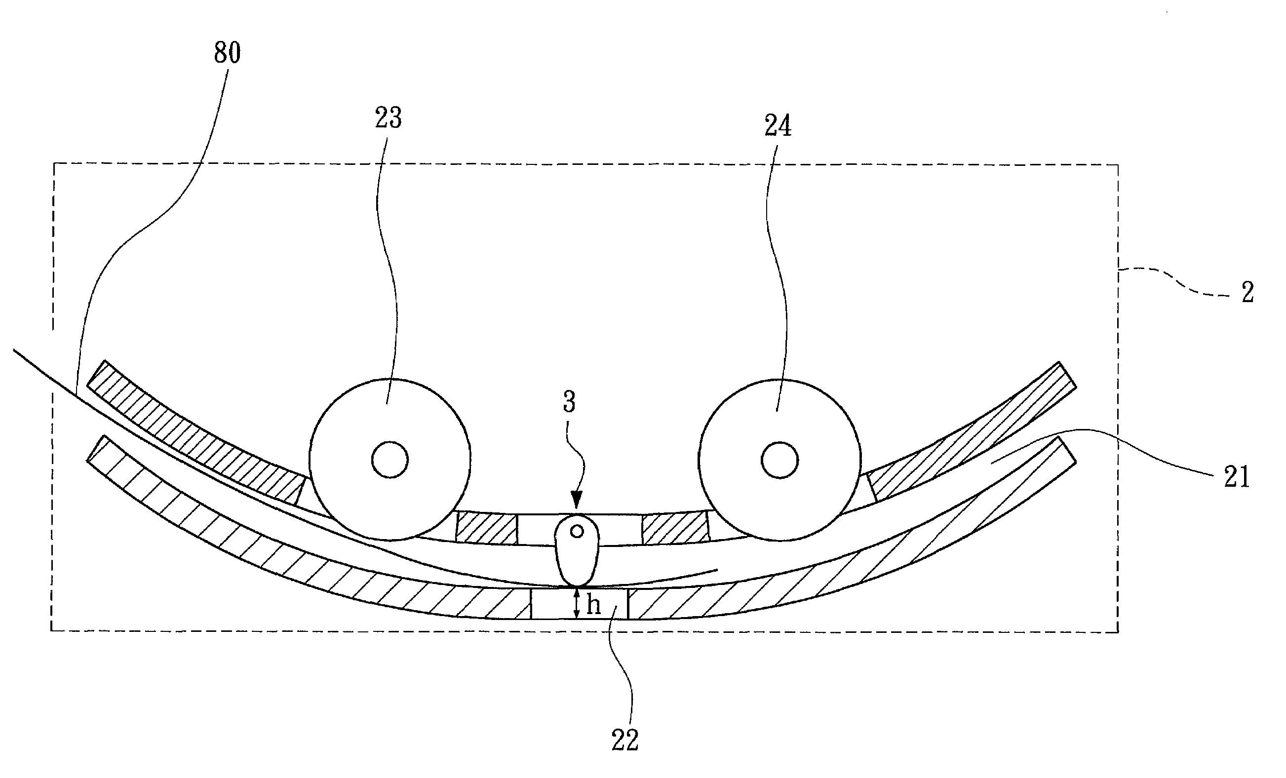
[0033]The main characteristic of the present invention is that the depth of field adjustment device for an automatic document feeder is provided an adjustable suppressing mechanism located at an appropriate position of the guiding groove in corresponding to the scanning window, and a depth of field height of the object to be scanned that passes through the scanning window may be adjusted by the adjustable suppressing device.

[0034]Please refer to FIG. 4A and FIG. 4B, which are the illustrations for the preferable position embodiment of the depth of field adjustment device for an automatic document feeder of the present invention. Wherein, when the flatbed-typed scanner proceeds the document-feeding-typed scanning, the flatbed-typed scanner carries an automatic document feeder 2 and then an optical chassis 15 is moved to the scanning zone of the automatic document feeder 2 and fixed afterwards. The automatic document feeder 2 has a guiding groove 21. A scanning window 22 is provided a...


PUM


Abstract

The present invention relates to a depth of field adjustment device and method for an automatic document feeder. The automatic document feeder has a guiding groove for placing an object to be scanned. The guiding groove has a scanning window for providing image picking-up for an optical chassis. An adjustable suppressing mechanism located at the guiding groove in corresponding to the scanning window may drive the object to be scanned to pass through an optimal depth of field height of the scanning window. First, at least a part of the pre-scanned object is fed in to be located between the adjustable suppressing mechanism and the scanning window. The depth of field height is then adjusted and changed by the adjustable suppressing mechanism. And, the image of the pre-scanned object is compared with a pre-stored image. After the pre-scanned objected has been judged to be located at the optimal depth of field height, the adjustable suppressing mechanism is fixed and the pre-scanned object is sent out. Then, it may achieve a most clear image picking-up for scanning the object to be scanned.

Description

FIELD OF THE INVENTION[0001]The present invention relates to a depth of field adjustment device and method, especially to a kind of depth of field adjustment device and method for an automatic document feeder that can adjust the locating height for the object to be scanned that is placed in the automatic document feeder and passes through the scanning window.BACKGROUND OF THE INVENTION[0002]High technology is progressing abruptly. Especially the technology for micro-electronic manufacture procedure is further innovated daily, so computer has already penetrated into each family and enterprise to become an indispensable electronic product in our daily lives. Following the prevalence of computer multimedia, more peripheral products are needed for the apparatus of input and output. And, because of the progress of the technology of the optical-electronic semiconductor, the product technology for relative peripheral devices for computer such as scanner, etc. has been more mature and preva...

Claims


Application Information

Patent Timeline
IPC IPC(8): H04N1/04H04N1/10H04N1/12
CPCH04N1/125H04N1/123H04N1/121H04N1/1017
Inventor FANG, PO-HUACHIANG, SHU-YA
Owner INTELLECTUAL VENTURES I LLC
Why Eureka
Try Eureka