Tiller-steered industrial truck

a technology of industrial trucks and steering wheels, which is applied in the direction of hand carts, hand carts with multiple axes, transportation and packaging, etc., can solve the problems of increasing the required operating force, limiting and affecting the maneuverability of standard industrial trucks

Inactive Publication Date: 2006-05-09
RAYMOND LTD
View PDF20 Cites 41 Cited by
  • Summary
  • Abstract
  • Description
  • Claims
  • Application Information

AI Technical Summary

Benefits of technology

[0006]One aspect of the present invention is an industrial truck that includes a pivot frame and a lift frame assembly, that has at least one fork, connected to the pivot frame. A steering assembly is rotatably connected to the pivot frame and is rotatable about a steering axis that is tilted toward the fork at a predetermined angle from vertical. The steering assembly includes a tiller that has a handle formed on its distal end to enable an operator to rotate the steering assembly about the steering axis. By tilting the steering axis toward the fork, the distal end of the tiller is also tilted toward the fork when it is in a fully turned position. This moves the handle toward the fork and away from any obstacle that may be near the back of the truck. This allows longer tillers to be used and larger / more comfortable handles to be used without increasing interference with obstacles near the back of the industrial truck.

Problems solved by technology

One problem inherent in standard industrial trucks is their maneuverability in tight spaces.
One thing that limits the maneuverability of standard industrial trucks is that they have a steering assembly 1 that has a steering axis A that is vertical.
However, shortening the tiller and / or reducing the size of the handle on these trucks leads to an increase in the required operating force, reduced comfort for the operator, compromise of the ergonomic design of the handle, and reduced performance of the truck.
In addition, even with shorter tillers and smaller handles, the position of the handle remains the limiting factor in the maneuverability of the truck.

Method used


Image

  • Tiller-steered industrial truck
  • Tiller-steered industrial truck
  • Tiller-steered industrial truck

Examples


Embodiment Construction

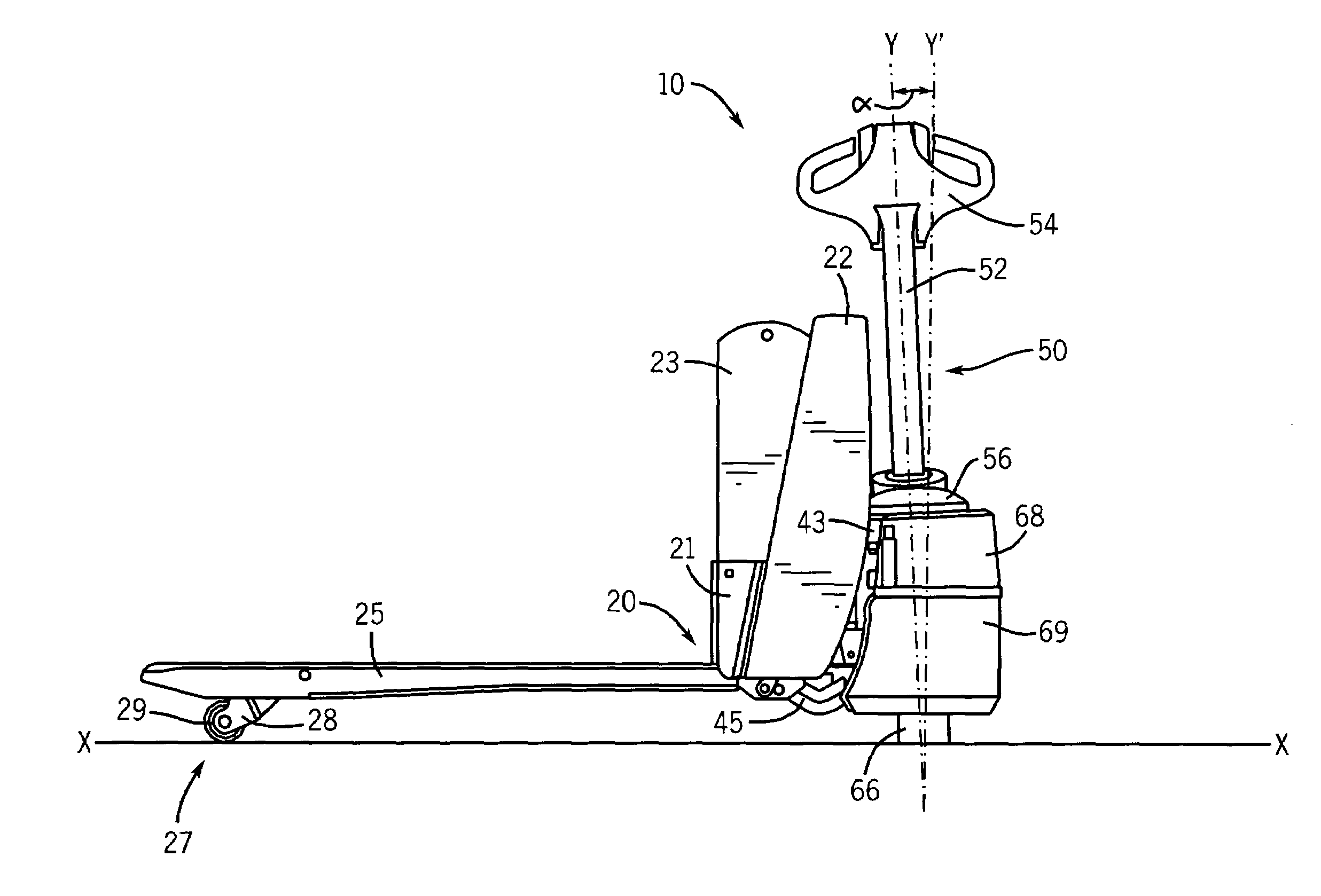
[0017]Referring to FIGS. 3–6, an industrial truck 10 according to the present invention is shown. Although the embodiment of the invention is described below in relation to a powered industrial truck, the present invention can be used on all tiller-steered industrial trucks (e.g. powered, manual, low-lift, stacker, special use, etc.). The industrial truck 10 comprises generally a conventional lift frame assembly 20, a pivot frame 40, a power unit 60, and a steering assembly 50.

[0018]The lift frame assembly 20 is used to support a pallet or other load when the industrial truck 10 is in use. The lift frame assembly 20 includes a pair of forks 24, 25, a battery box 21, and an upper wrapper 22, which are welded or otherwise fastened together. A pair of load wheel assemblies 26, 27 are rotatably fastened to the forks 24, 25 towards the distal end of the forks 24, 25. The load wheel assemblies 26, 27 include wheel forks 28 and load wheels 29 and are used to provide support to the distal e...


PUM


Abstract

An industrial truck having a steering assembly used to steer the industrial truck about a steering axis when a pivotally attached tiller is swung around the truck by an operator. The steering axis is tilted towards the forks of the truck an angle between 2 and 5 degrees from vertical. By tilting the pivot axis, the distal end of the tiller is tilted toward the forks of the truck when rotated to a fully turned position. This improves the maneuverability of the truck near obstacles and allows longer tillers and larger / more comfortable handles to be used without increasing interference with obstacles near the back of the truck.

Description

FIELD OF THE INVENTION[0001]The present invention relates to tiller-steered industrial trucks. In particular, the present invention relates to steering assemblies used with tiller-steered industrial trucks.BACKGROUND OF THE INVENTION[0002]As shown in FIGS. 1 and 2, standard tiller-steered industrial trucks, referred to herein as industrial trucks, have a steering assembly 1 that is used to steer the truck. The steering assembly 1 typically includes a tiller 2 and a handle 4 fastened to the distal end of the tiller 2. In some manual trucks, in addition to providing steering, the tiller 2 can also be used as a mechanism to provide lift (by interconnecting the tiller with a hydraulic cylinder or other lift mechanism) and to provide manual motive force to move the truck. The steering assembly 1 is also interconnected with a drive wheel 6 such that as the steering assembly 1 is rotated, the drive wheel 6 also rotates with the steering assembly 1.[0003]One problem inherent in standard ind...

Claims


Application Information

Patent Timeline
Patent Type & Authority Patents(United States)
IPC IPC(8): B62D51/04B62B3/06B62B5/06
CPCB62B3/0612B62B5/063
Inventor TOOMEY, MARK
Owner RAYMOND LTD
Why Eureka
Try Eureka