Well Service Pump System

a well service pump and pump body technology, applied in the direction of pump control, pump unit, positive displacement liquid engine, etc., can solve the problems of reducing the stroke length of the plunger, reducing the size of the frac unit mounted on the trailer, and causing the failure rate of the current frac pump fluid end,

Active Publication Date: 2015-07-09
AMERIFORGE GRP
View PDF10 Cites 145 Cited by
  • Summary
  • Abstract
  • Description
  • Claims
  • Application Information

AI Technical Summary

Benefits of technology

[0016]In some embodiments of the present well service pump systems, the source of driving fluid comprises: a diesel engine; a hydraulic drive gear box coupled to an output shaft of the diesel engine; and one or more hydraulic pumps coupled to the hydraulic drive gear box. In some embodiments, the hydraulic pump(s) each comprises a variable-displacement hydraulic pump. In some embodiments, the working fluid pump assemblies do not include a crank shaft, and the system does not include an automatic transmission. In some embodiments, in each working fluid pump assembly: the ram cylinder housing includes a first port on a first side of the ram piston and second port on a second side of the ram piston.
[0017]In some embodiments of the present well service pump systems, each working fluid pump assembly further comprises: an inlet check valve coupled to the end cylinder housing and configured to permit working fluid to be drawn into the end cylinder housing but prevent working fluid from exiting the end cylinder housing through the inlet check valve; and an outlet check valve coupled to the end cylinder housing and configured to permit working fluid to exit the end cylinder housing while preventing working fluid from being drawn into the end cylinder housing. In some embodiments, in each working fluid pump assembly, the outlet check valve and inlet check valve are each disposed at least partially in the end cylinder housing. Some embodiments Some embodiments further comprise: a suction manifold coupled to the inlet check valves of the working fluid pump assemblies; and a discharge manifold coupled to the outlet check valves of the working fluid pump assemblies. In some embodiments, the suction manifold includes a plurality of inlet flow channels each coupled to a different one of the working fluid pump assemblies via the corresponding inlet check valve, each inlet flow channel having a cross-sectional area at least as large as the cross-sectional area of the interior of the working fluid end cylinder of the coupled working fluid pump assembly. In some embodiments, the discharge manifold includes a plurality of outlet flow channels each coupled to a different one of the working fluid pump assemblies via the corresponding outlet check valve, each outlet flow channel having a cross-sectional area that is smaller than the cross-sectional area of the interior of working fluid end cylinder of the coupled working fluid pump assembly. In some embodiments, the valve system further comprises for each of the working fluid pump assemblies: a directional control valve coupled to the source of pressured driving fluid and configured to selectively direct pressurized driving fluid to the first port or to the second port. In some embodiments, each working fluid pump assembly is configured such that directing pressurized driving fluid to the first port instead of the second port actuates the hydraulic ram cylinder to drive the plunger rod in the first direction, and directing pressurized fluid to the second port instead of the first port actuates the hydraulic ram to drive the plunger rod in the second direction. In some embodiments, the directional control valve is configured to be electronically controlled to control of the position of the corresponding piston.
[0018]In some embodiments of the present well service pump systems, the control system comprises a processor or programmable logic controller (PLC) configured to sequentially actuate the working fluid pump assemblies such that the hydraulic ram cylinder of a first one of the working fluid pump assemblies is beginning its forward stroke as the hydraulic ram cylinder of a second one of the working fluid pump assemblies is ending its forward stroke. In some embodiments, the processor or PLC is configured to sequentially actuate the working fluid pump assemblies such that the hydraulic ram cylinder of a third one of the working fluid pump assemblies is beginning its forward stroke when the hydraulic ram cylinder of the first one of the working fluid pump assemblies is one half of the way through its forward stroke. In some embodiments, the two or more working fluid pump assemblies comprises a number of working fluid pump assemblies that is a multiple of three. In some embodiments, the processor or PLC is configured to actuate each of the working fluid pump assemblies, via adjustment of the source of pressurized working fluid and / or adjustment of the valve system, such that the duration of the forward stroke is twice the duration of the return stroke. In some embodiments, the control system further comprises: a plurality of position sensors each coupled to a different one of the hydraulic ram cylinders and configured to detect the position of the ram piston in the ram cylinder housing. In some embodiments, the processor of PLC is coupled to the plurality of position sensors and is further configured to adjust the timing of actuation of the working fluid pump assemblies based on the detected positions of the ram pistons.
[0019]Some embodiments of the present well service pumps (e.g., for delivering fracturing fluid at high pressure to a well) comprise: a working fluid end cylinder having an end cylinder housing, a plunger rod configured to reciprocate in the end cylinder housing; a hydraulic ram cylinder (e.g., having a ram cylinder housing, a ram piston configured to reciprocate in the ram cylinder housing, and a piston rod coupled to the ram piston and configured to be coupled to the plunger rod of the working fluid end cylinder such that piston of the hydraulic ram cylinder can be actuated to move the plunger rod of the working fluid end cylinder: in a first direction to expel working fluid from the end cylinder housing during a forward stroke of the plunger rod, and in a second direction to draw working fluid into the end cylinder housing during a return stroke of the plunger rod). In some embodiments, each working fluid pump assembly further comprises: a coupling member configured to couple to the plunger rod of the working fluid end cylinder and to the piston rod of the hydraulic ram cylinder. In some embodiments, the piston rod is configured to be coupled in a axially aligned relation to the plunger rod. In some embodiments, the end cylinder housing of the working fluid end cylinder has a cylindrical inner wall defining an end cylinder inner diameter, the plunger rod has an outer surface that is spaced apart from the cylindrical inner wall such that the working fluid end cylinder can pump abrasive fluids without the plunger rod and the end cylinder inner wall simultaneously contacting individual particles in the working fluid. In some embodiments, the outer diameter of the plunger rod is between 70 percent and 98 percent of the inner diameter of the cylindrical inner wall. In some embodiments, the outer diameter of the plunger rod is between 85 percent and 95 percent of the inner diameter of the cylinder inner wall. In some embodiments, the plunger rod has a length that exceeds 12 inches (e.g., exceeds 40 inches and / or is between 50 inches and 60 inches).
[0020]In some embodiments of the present well service pumps, the ram cylinder housing includes a first port on a first side of the ram piston and second port on a second side of the ram piston. Some embodiments further comprise: an inlet check valve coupled to the end cylinder housing and configured to permit working fluid to be drawn into the end cylinder housing but prevent working fluid from exiting the end cylinder housing through the inlet check valve; and an outlet check valve coupled to the end cylinder housing and configured to permit working fluid to exit the end cylinder housing while preventing working fluid from being drawn into the end cylinder housing. In some embodiments, the outlet check valve and inlet check valve are each disposed at least partially in the end cylinder housing. Some embodiments further comprise: a position sensor coupled to at least one of the hydraulic ram cylinder and the working fluid end cylinder. Some embodiments further comprise: a position indicator coupled to at least one of the piston, piston rod, and plunger rod.

Problems solved by technology

There are a number of known problems with the prior art plunger pumps of the type under consideration.
As a result, this necessarily means that the frac units which are trailer mounted will be restricted in size by the applicable DOT rules and regulations.
However, reducing the stroke length of the plungers is not an ideal solution to the problem and, in fact, offers a number of disadvantages in the design.
This is due to the fact that there is a tremendous failure rate in current frac pump fluid ends, due to cyclic fatigue.
The increased failure rate results from increased demand placed upon today's frac pumps, as compared to the practice in prior years.
This type of operation may exceed the intended design limits of the units.
However, these designs still suffer from all of the problems of having the frac pump mounted at a right angle to the engine, transmission and driveline.
They also fail to reduce the mechanical complexity of the system and, in fact, likely increase the complexity.
With prior art designs, it will be very difficult to increase the plunger stroke length much more than 10 to 12 inches.
This can put frac pumps in violation of DOT standards regarding the width of the trailer mounted frac unit, since the pump sits at a right angle to the engine, transmission and driveline.

Method used


Image

  • Well Service Pump System
  • Well Service Pump System
  • Well Service Pump System

Examples


Embodiment Construction

[0044]The following drawings illustrate by way of example and not limitation. For the sake of brevity and clarity, every feature of a given structure is not always labeled in every figure in which that structure appears. Identical reference numbers do not necessarily indicate an identical structure. Rather, the same reference number may be used to indicate a similar feature or a feature with similar functionality, as may non-identical reference numbers. The figures are drawn to scale (unless otherwise noted), meaning the sizes of the depicted elements are accurate relative to each other for at least the embodiment depicted in the figures.

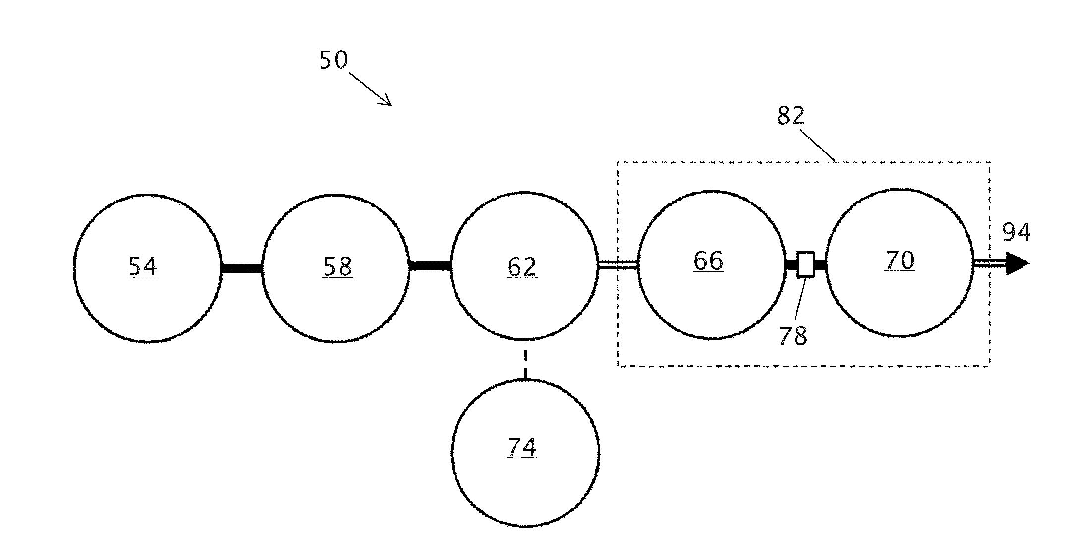
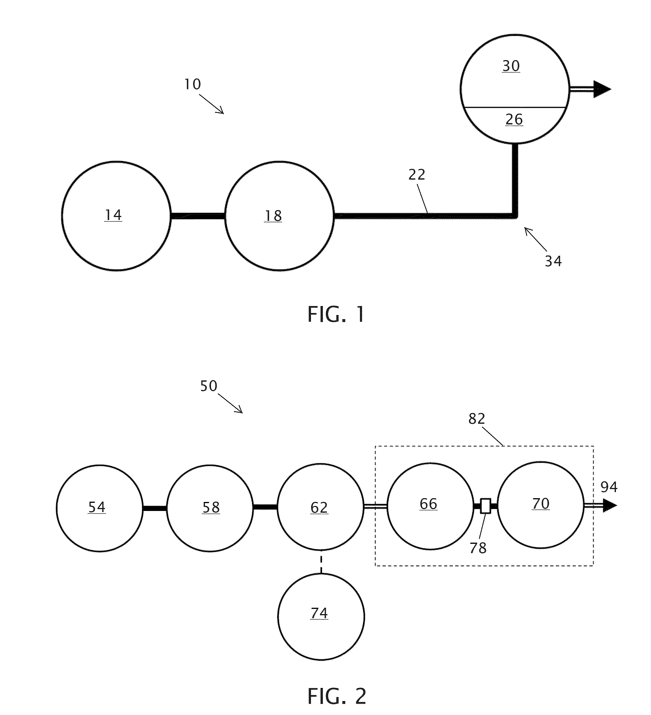
[0045]FIG. 1 is a simplified, schematic flow diagram of a prior art well service pump system 10 of the type toward which the improvements of the present invention are directed. As has been briefly discussed, such well service pumps typically utilize a diesel engine 14, which will usually be 2,000 bhp or larger. The diesel engine transfers its power ...


PUM


Abstract

A well service pump system supplies high pressure working fluid to a well. The pump system is a linear design which incorporates a diesel engine, a hydraulic drive gear box, open loop hydraulic Pumps, hydraulic ram cylinders, controls for the hydraulic system hydraulic cylinders, working fluid end cylinders and a coupling to connect the hydraulic cylinders and the working fluid ends. The engine powers the hydraulic system which, in turn, provides hydraulic fluid to operate the hydraulic ram cylinders. Each of the polished rods of the hydraulic ram cylinders is connected axially to a plunger rod end of a working fluid end cylinder. There is no crankshaft or automatic transmission required. The linear design allows for a longer plunger stroke length while still allowing highway transport on a truck or skid.

Description

CROSS-REFERENCE TO RELATED APPLICATIONS[0001]The application claims priority to U.S. Provisional Patent Application No. 61 / 865,331 filed Aug. 13, 2013, which is incorporated by reference in its entirety.BACKGROUND[0002]1. Field of Invention[0003]The present invention relates generally to pumping assemblies used for well servicing applications, most particularly pumping assemblies used for well fracturing operations.[0004]2. Description of Related Art[0005]Oil and gas wells require services such as fracturing, acidizing, cementing, sand control, well control and circulation operations. All of these services require pumps for pumping fluid down the well. The type of pump that has customarily been used in the industry for many years is a gear driven plunger type, which may be referred to as a “frac pump.” The pump is often powered by a diesel engine, typically 2,000 bhp or larger, that transfers its power to a large automatic transmission. The automatic transmission then transfers the ...

Claims


Application Information

Patent Timeline
Patent Type & Authority Applications(United States)
IPC IPC(8): F04B23/06F04B47/02F04B9/111F04B7/02F04B17/05F04B13/00
CPCF04B23/06F04B17/05F04B47/02F04B9/111F04B7/02F04B13/00
Inventor BRIDGES, BILL P.
Owner AMERIFORGE GRP
Why Eureka
Try Eureka