Waste heat recovery apparatus

Inactive Publication Date: 2009-03-19
DENSO CORP +1
View PDF7 Cites 115 Cited by
  • Summary
  • Abstract
  • Description
  • Claims
  • Application Information

AI Technical Summary

Benefits of technology

[0018]In this case, although a pressure differential occurs between the inlet and the outlet of the expansion unit, the operation rotational speed of the rotary electric machine is increased relative to the predetermined rotational speed in accordance with the pressure differential. With this, an operation rotational speed of the expansion unit is increased, and a di

Problems solved by technology

However, if the pressure of the refrigerant on a low-pressure side (pressure on the outlet side) flowing out from the expansion unit is too high, it is difficult to sufficiently maintain the pressure differential between the high-pressure side and the low-pressure side, and thus over-expansion may take place.
That is, if the e

Method used


Image

  • Waste heat recovery apparatus
  • Waste heat recovery apparatus
  • Waste heat recovery apparatus

Examples


first embodiment

[0046]A first embodiment of the present invention will now be described with reference to FIGS. 1 to 11.

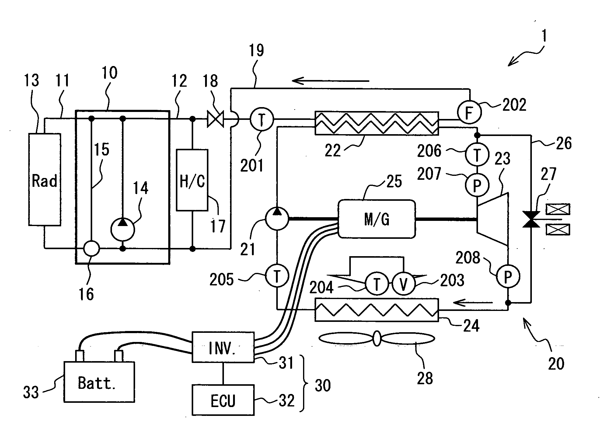
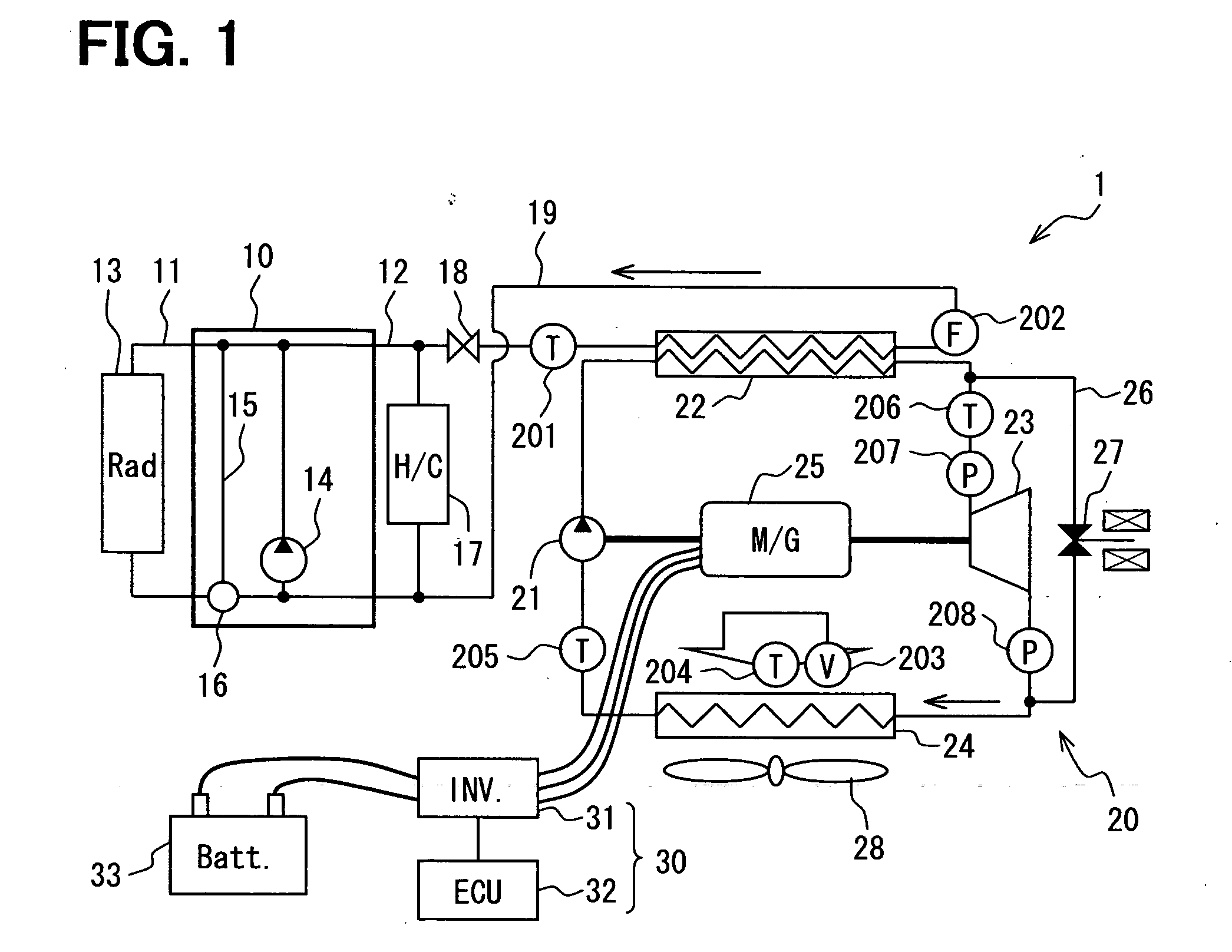
[0047]FIG. 1 is a diagram schematically illustrating the whole system of a waste heat recovery apparatus 1 having a Rankine cycle 20. As shown in FIG. 1, the waste heat recovery apparatus 1 of the present embodiment is applied, for example, to a vehicle that uses an engine 10 as a driving source.

[0048]The engine 10 is a water-cooled internal combustion engine. The engine 10 is provided with a radiator circuit 11 for cooling the engine 10 by circulating the engine-cooling water, and a heater circuit 12 for heating air to be conditioned by using the cooling water (hot water) as a source of heat.

[0049]A radiator 13 is provided in the radiator circuit 11. The radiator 13 cools the cooling water circulated by a hot water pump 14 by exchanging heat with an external air. The hot water pump 14 may be either an electric pump or a mechanical pump. A heater 22 of the Ranking cycle 20, which ...

second embodiment

[0125]Next, a second embodiment of the present invention will be described with reference to FIGS. 12 and 13. In the present embodiment, steps common to those of the first embodiment are denoted by the same reference numerals as those of the first embodiment, and described below are portions different from those of the first embodiment.

[0126]FIG. 12 is a flowchart illustrating the Rankine operation control (S4) according to the present embodiment in detail. In the present embodiment, the Rankine operation control (S4) has a maximum / minimum rotational speed setting step (S411), which is different from the first embodiment. The constitution of devices and other controls are the same as those of the first embodiment. Therefore, described below in detail is the maximum / minimum rotational speed setting step (S411), and other portions are not described again.

[0127]Referring to FIG. 12, at step S411, an increase or decrease of the maximum rotational speed Nmax_s of the expansion unit 23 is...

modified examples of first and second embodiments

[0138]In the above first embodiment, the pressure information P as the low-pressure side condition was the outlet-side pressure Pex_out of the expansion unit 23. Instead, the pressure information P may be, for example, a differential pressure ΔP (inlet-side pressure Pex_in—outlet-side pressure Pex_out) between the pressure Pex_in on the inlet side and the pressure Pex_out on the outlet side of the expansion unit 23. In this case, the diagram of characteristics shown in FIG. 14 can be used, in place of the diagram of characteristics explained in FIG. 8, to obtain the same effect as that of the above first embodiment.

[0139]In the diagram of characteristics (FIG. 9) in which the battery voltage is taken into consideration at step S44 (see FIGS. 6 and 12) in the first and second embodiments, the command rotational speed N_id may be continuously varied instead of being varied stepwise. In this case, the diagram of characteristics shown in FIG. 15 can be used. When the battery voltage lie...


PUM


Abstract

A waste heat recovery apparatus including a Rankine cycle which includes a heater for heating an operation fluid by waste heat from a heat-generating device, an expansion unit for converting energy of expansion of the operation fluid flowing out from the heater into mechanical energy, and a condenser for condensing and liquefying the expanded operation fluid, a temperature detector for detecting the temperature of the operation fluid on the inlet side of the expansion unit, a pressure detector for detecting inlet-side pressure of the expansion unit, a pressure detector for detecting outlet-side pressure of the expansion unit, and a control unit. The control unit controls a command rotational speed of the expansion unit based on superheated degree information at the inlet of the expansion unit obtained from the operation fluid temperature and the inlet-side pressure, and pressure information in which the outlet-side pressure is considered.

Description

CROSS REFERENCE TO RELATED APPLICATION[0001]This application is based on Japanese Patent Applications No. 2007-239962 filed on Sep. 14, 2007 and No. 2007-268329 filed on Oct. 15, 2007, the disclosure of which is incorporated herein by reference.FIELD OF THE INVENTION[0002]The present invention relates to a waste heat recovery apparatus for recovering the power by utilizing waste heat from a heat-generating device such as an internal combustion engine of a vehicle.BACKGROUND OF THE INVENTION[0003]A waste heat recovery apparatus has heretofore been known for recovering the power by utilizing the waste heat from an internal combustion engine. The waste heat recovery apparatus has a Rankine cycle including a heater for heating an operation fluid by using the waste heat from an internal combustion engine, an expansion unit (turbine) for producing a rotational driving force by expanding the heated operation fluid, and a condenser for condensing the expanded operation fluid.[0004]According...

Claims


Application Information

Patent Timeline
IPC IPC(8): F01K23/06
CPCF01K13/02Y02T10/166F02G5/02Y02T10/12
Inventor NISHIKAWA, MICHIOYAMASHITA, KOUJIKISHITA, HIROSHIUNO, KEIICHI
Owner DENSO CORP
Why Eureka
Try Eureka