Compression stripping of flue gas with energy recovery

a technology of compression stripping and flue gas, which is applied in the direction of greenhouse gas reduction, separation processes, lighting and heating apparatus, etc., can solve the problems of significant energy required to compress flue gas and the dramatic drop in power plant thermal efficiency, so as to reduce auxiliary power requirements and reduce costs

Inactive Publication Date: 2005-05-31
THE UNITED STATES AS REPRESENTED BY THE DEPARTMENT OF ENERGY
View PDF21 Cites 120 Cited by
  • Summary
  • Abstract
  • Description
  • Claims
  • Application Information

AI Technical Summary

Benefits of technology

[0005]In the invention, the power generation combustion systems recirculate (recycle) wet flue gas, condense H2O, and acid gases such as CO2, SOX, and NOX and capture particulates. Using this invention, we remove multiple pollutants through the integrated condensation of H2O and CO2 with entrainment of particulates and dissolution and condensation of other pollutants including SO2. Consolidating the removal of pollutants into one process has the potential to reduce costs and reduce auxiliary power requirements. Non-condensable combustion products including oxygen, argon, and nitrogen are present in combustion products. Specifically, argon and nitrogen can come from the air separation process (remaining in the produced oxygen) and nitrogen can also be present in the fuel. Oxygen is normally supplied in excess to ensure complete combustion and therefore is found in the combustion products. Condensable vapors such as H2O, CO2, SOx, and NOx are produced in the combustion process and are the targets for condensation in this invention. When referring to combustion products in this invention it is assumed that these condensable vapors and non-condensable gases are present as well as particulats and other pollutants.

Problems solved by technology

There is significant energy required to compress flue gas.
If the energy of compression is not minimized and partially recovered the power plant thermal efficiency will drop dramatically.

Method used


Image

  • Compression stripping of flue gas with energy recovery
  • Compression stripping of flue gas with energy recovery
  • Compression stripping of flue gas with energy recovery

Examples


Embodiment Construction

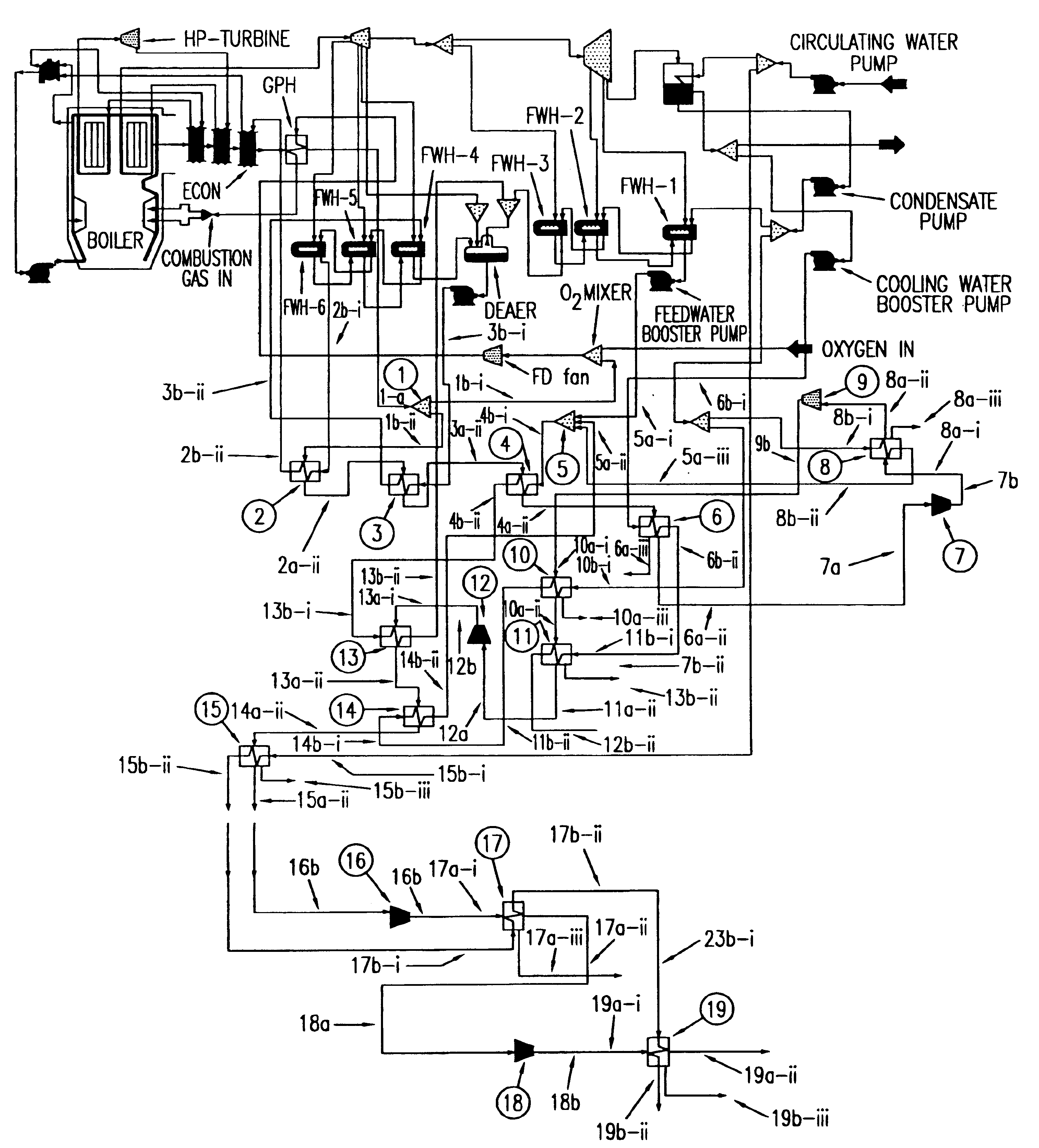
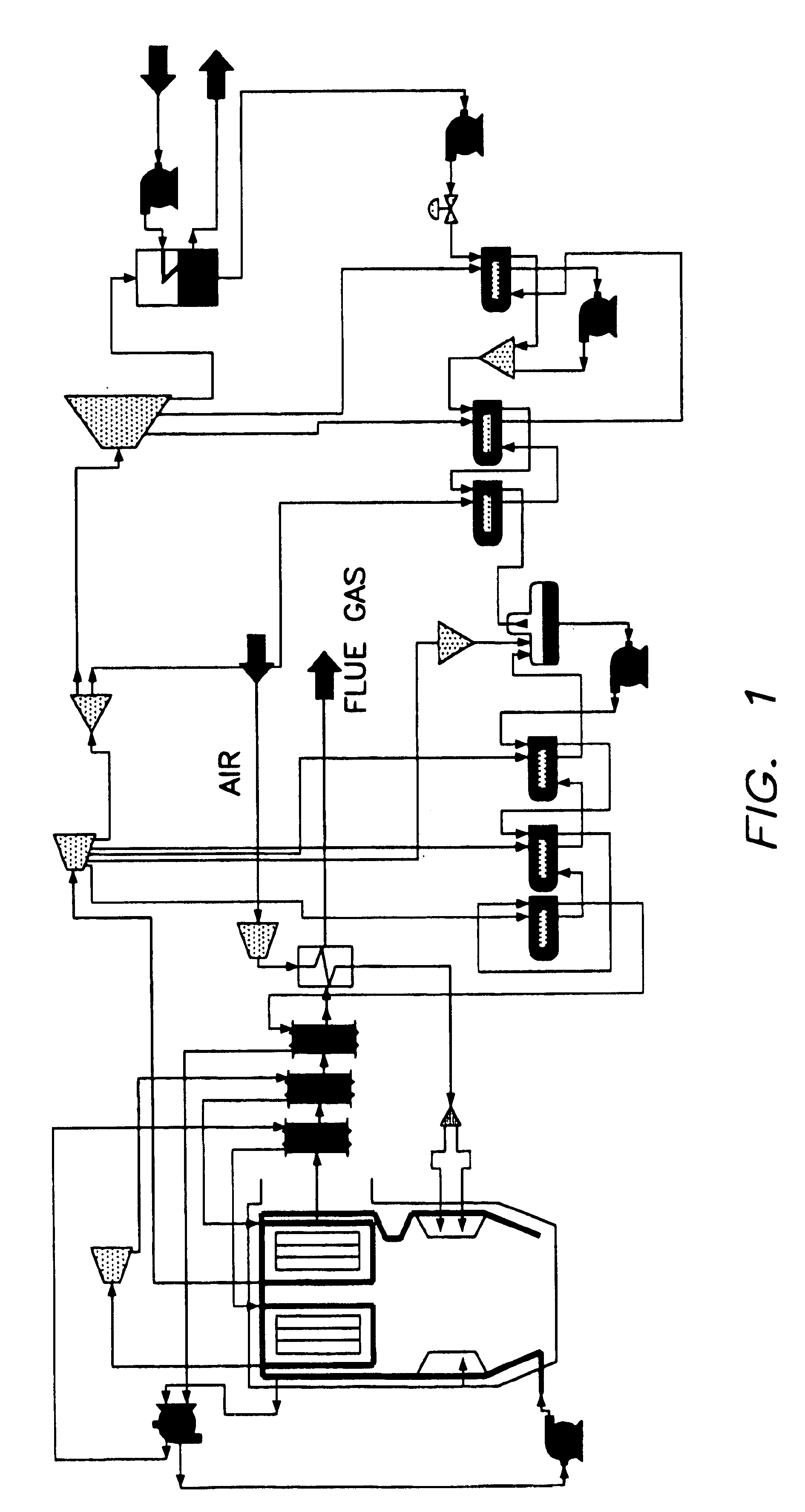
[0014]We have used computer modeling using GateCycle™ modeling software to examine energy recovery in two power plant designs which recover CO2 and SO2. The basic models include a subcritical single reheat PC unit (2,400 psi (16.55 MPa), 1,004° F. (540° C.), 1,004° F. (540° C.)) see FIG. 1, and a mildly supercritical double reheat PC unit (3,500 psi (24.13 MPa), 1,050° F. (566° C.), 1,050° F. (566° C.), 1,050° F. (566° C.)). The CO2 in the flue gas is removed and converted to liquid (or supercritical fluid) form at pressures suitable for transmission through a pipeline (2,000-5,000 psi (13.8-34.5 MPa). While this modeling effort examined standard subcritical and supercritical systems, there is no reason to restrict these principles to the two configurations studied here. The design of the subcritical unit is based on an example model provided with the power plant modeling software (GateCycle™).

[0015]The supercritical power generation unit model was developed based on the heat balanc...


PUM

PropertyMeasurementUnit
pressuresaaaaaaaaaa
temperatureaaaaaaaaaa
poweraaaaaaaaaa

Abstract

A method of remediating and recovering energy from combustion products from a fossil fuel power plant having at least one fossil fuel combustion chamber, at least one compressor, at least one turbine, at least one heat exchanger and a source of oxygen. Combustion products including non-condensable gases such as oxygen and nitrogen and condensable vapors such as water vapor and acid gases such as SOX and NOX and CO2 and pollutants are produced and energy is recovered during the remediation which recycles combustion products and adds oxygen to support combustion. The temperature and/or pressure of the combustion products are changed by cooling through heat exchange with thermodynamic working fluids in the power generation cycle and/or compressing and/or heating and/or expanding the combustion products to a temperature/pressure combination below the dew point of at least some of the condensable vapors to condense liquid having some acid gases dissolved and/or entrained and/or directly condense acid gas vapors from the combustion products and to entrain and/or dissolve some of the pollutants while recovering sensible and/or latent heat from the combustion products through heat exchange between the combustion products and thermodynamic working fluids and/or cooling fluids used in the power generating cycle. Then the CO2, SO2, and H2O poor and oxygen enriched remediation stream is sent to an exhaust and/or an air separation unit and/or a turbine.

Description

CONTRACTUAL ORIGIN OF THE INVENTION[0001]The United States Government has rights in this invention pursuant to employer / employee agreements between the U.S. Department of Energy (DOE) and the inventors.BACKGROUND OF THE INVENTION[0002]Pollutant removal is an integral part of all modern power plant designs. As the pollution control requirements become more stringent, the energy demands for capturing those pollutants become greater. Recirculating (recycling) flue gas with oxygen injection offers the potential for the efficient simultaneous removal of multiple pollutants and CO2 in both retrofits and new power plants. In recirculation of flue gas, the combustion products which are normally sent up the smoke stack at a standard power plant, are recycled back into the boiler after the injection of sufficient oxygen to ensure that the fuel can burn in the mixed gas. A small portion of the flue gas (approximately ¼) is removed from the system. In our approach, this portion of the flue gas ...

Claims


Application Information

Patent Timeline
Patent Type & Authority Patents(United States)
IPC IPC(8): F23C9/00F23J15/06F23L7/00
CPCF23C9/00F23J15/06F23L7/00F23J2219/70F23J2900/15061Y02E20/363F23L2900/07001F23L2900/07007Y02E20/322Y02E20/344Y02E20/30Y02E20/32Y02E20/34
Inventor OCHS, THOMAS L.O'CONNOR, WILLIAM K.
Owner THE UNITED STATES AS REPRESENTED BY THE DEPARTMENT OF ENERGY
Why Eureka
Try Eureka