Well service pump power system and methods

a power system and well technology, applied in the direction of piston pumps, surveying, borehole/well accessories, etc., can solve the problems of increasing the cost and complexity of frac pumps

Pending Publication Date: 2019-10-31
AMERIFORGE GRP
View PDF0 Cites 117 Cited by
  • Summary
  • Abstract
  • Description
  • Claims
  • Application Information

AI Technical Summary

Benefits of technology

[0011]In some embodiments of the present disclosure, a method of powering a pump system includes: operating an electric motor configured to power the plurality of pumps; and operating, by a control system coupled to a variable frequency drive (VFD) and configured to control, for each of the plurality of pumps, the VFD, where the VFD is coupled to the electric motor to control an amplitude of power provided by the electric motor to the plurality of pumps. In some embodiments, the operating the VFD includes: coupling, by the control system, the VFD to one of the pumps while decoupling the VFD from the other pumps; actuating a first state, wherein the pump is powered by the electric motor and the amplitude of power provided by the electric motor to the pump is controlled by the VFD, on the one of the pumps coupled to the VFD; decoupling the VFD from the one of the pumps; actuating a second state, wherein the pump is powered by the electric motor and the amplitude of power provided by the electric motor to the pump is not controlled by the VFD; coupling the VFD to one of the other pumps; actuating the first state on the one of the other pumps coupled to the VFD; decoupling the VFD from the one of the other pumps; and actuating the second state on the one of the other pumps.
[0012]In some embodiments, actuating the first state includes actuating a VFD flow path that, in the first state, permits electricity to flow through the VFD flow path and allows the VFD to control the amplitude of power provided by the electric motor to the pump. In some embodiments, actuating the VFD flow path includes: transmitting, by the control system coupled to a plurality of switches, an ON signal to one of the switches, where each switch couples one of the pumps to the VFD; switching the...

Problems solved by technology

However, using multiple VFDs increase...

Method used


Image

  • Well service pump power system and methods
  • Well service pump power system and methods
  • Well service pump power system and methods

Examples


Embodiment Construction

[0030]The following drawings illustrate by way of example and not limitation. For the sake of brevity and clarity, every feature of a given structure is not always labeled in every figure in which that structure appears. Identical reference numbers do not necessarily indicate an identical structure. Rather, the same reference number may be used to indicate a similar feature or a feature with similar functionality, as may non-identical reference numbers. The figures are drawn to scale (unless otherwise noted), meaning the sizes of the depicted elements are accurate relative to each other for at least the embodiment depicted in the figures.

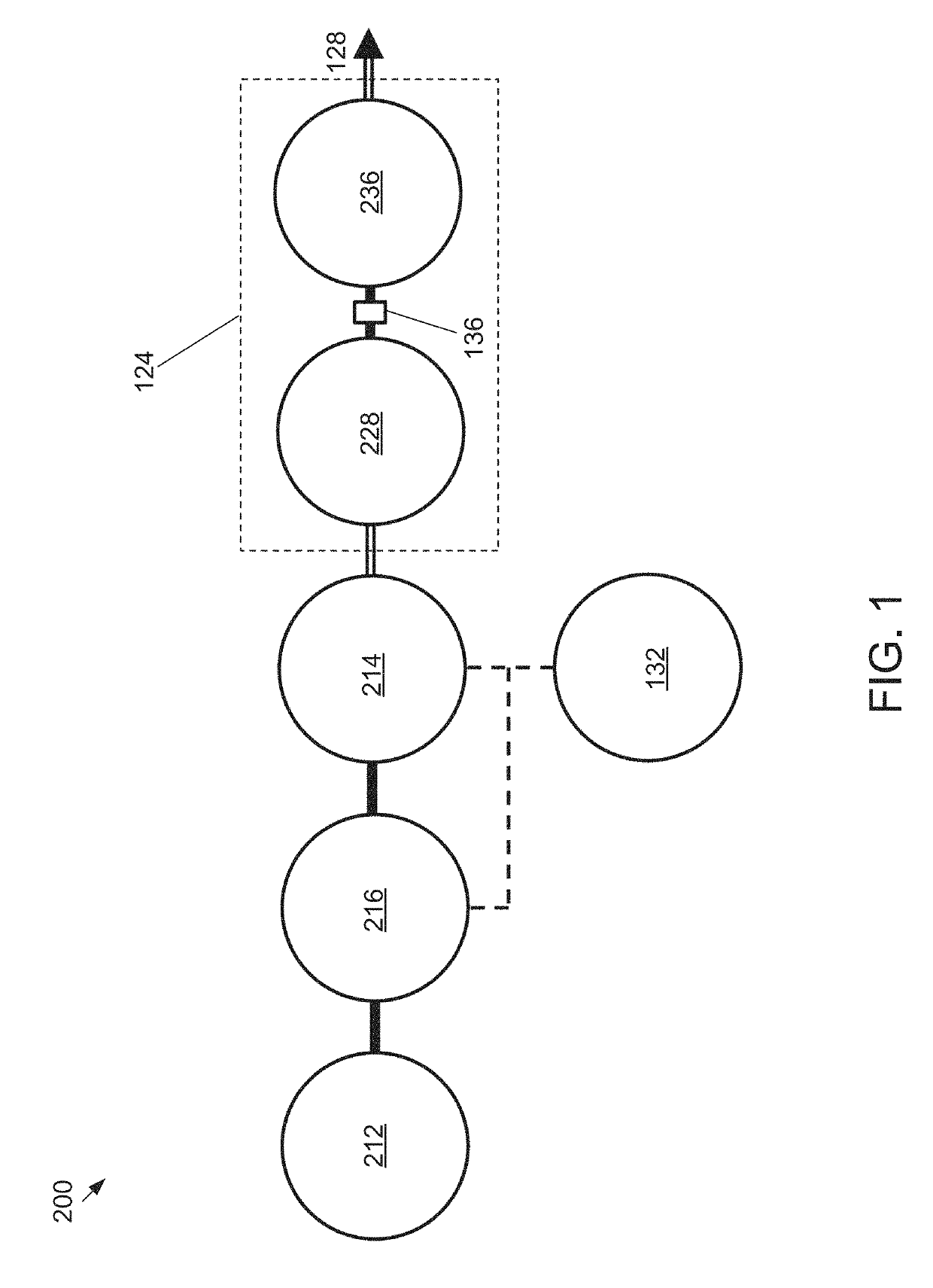
[0031]FIG. 1 is a simplified, schematic diagram of the operative components of an embodiment of the present well service pump system 200. In the embodiment shown, system 200 includes an electric motor 212 coupled to a variable frequency drive (VFD) 216. The VFD 216 selectively couples the electric motor 212 to one of a plurality of hydraulic pumps 2...


PUM


Abstract

A well service pump system supplies high pressure working fluid to a well. The pump system is a linear design which incorporates an electric motor, a variable frequency drive (VFD), a pump drive, closed loop variable flow rate hydraulic pumps, hydraulic ram cylinders, working fluid end cylinders, and a coupling to connect the hydraulic ram cylinders and the working fluid end cylinders. The electric motor powers the hydraulic system which, in turn, provides hydraulic fluid to operate the hydraulic ram cylinders. The VFD is connected to a single one of the hydraulic pumps at a time and applies power to the connected pump, via the pump drive, to drive the connected pump from a cold start to an operating speed. The VFD is connected sequentially, one pump at a time, to each of the hydraulic pumps and disconnected from each pump once the pump reaches the operating speed. Once the pump reaches operating speed, the pump is connected to receive power directly to the electric motor.

Description

CROSS-REFERENCE TO RELATED APPLICATIONS[0001]This application claims priority to U.S. Provisional Application No. 62 / 664,078, filed Apr. 27, 2018, the entire contents of which application are specifically incorporated by reference herein without disclaimer.BACKGROUND1. Field of Invention[0002]The present invention relates generally to power systems for pumping assemblies used for well servicing applications, most particularly powering pumping assemblies used for well fracturing operations with an electric motor and a variable frequency drive (VFD).2. Description of Related Art[0003]Oil and gas wells require services such as fracturing, acidizing, cementing, sand control, well control and circulation operations. All of these services require pumps for pumping fluid down the well. The type of pump that has customarily been used in the industry for many years is a gear driven plunger type, which may be referred to as a “frac pump.” The pump is often powered by a diesel engine, typicall...

Claims


Application Information

Patent Timeline
IPC IPC(8): F04D13/08E21B4/14E21B47/00E21B43/12
CPCE21B43/129E21B44/005F04D13/08E21B4/14E21B47/0008F04B9/10F04B15/02F04B17/03F04B17/06F04B23/06F04B49/065F04B47/04F04B49/20
Inventor GABLE, TOMSMITH, GARRETTBURNETT, SHELTONFISHER, JOHN
Owner AMERIFORGE GRP
Why Eureka
Try Eureka