Laser dazzler matrix

a laser and matrix technology, applied in the field of laser systems, can solve the problems of loss of visual sensitivity, degrade vision, and difficulty in seeing the direction of light sources

Inactive Publication Date: 2006-05-09
CHEMRING DETECTION SYST
View PDF17 Cites 61 Cited by
  • Summary
  • Abstract
  • Description
  • Claims
  • Application Information

AI Technical Summary

Problems solved by technology

For example, high-intensity light can present a glare that degrades vision, makes it difficult to see the direction of the light source, and causes discomfort while in the visual field of the observer.
High-intensity light can also momentarily blind (“flashblind”) the viewer, causing a significant effect on the retinal adaptation level resulting in a loss of visual sensitivity after the light source is removed, and can even promote physiological responses such as disorientation and nausea.
However, excessive exposure to laser radiation can cause permanent eye damage and blindness.
These devices suffer from a significant drawback in that the collimated light beam must diverge rapidly to prevent it from being too intense at short distances, which has the result of making the device effective only over relatively short distances.

Method used


Image

  • Laser dazzler matrix
  • Laser dazzler matrix
  • Laser dazzler matrix

Examples


Embodiment Construction

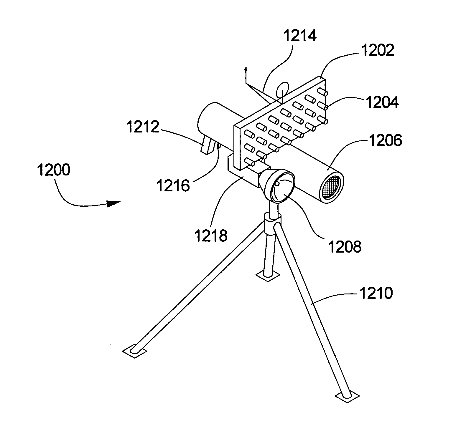
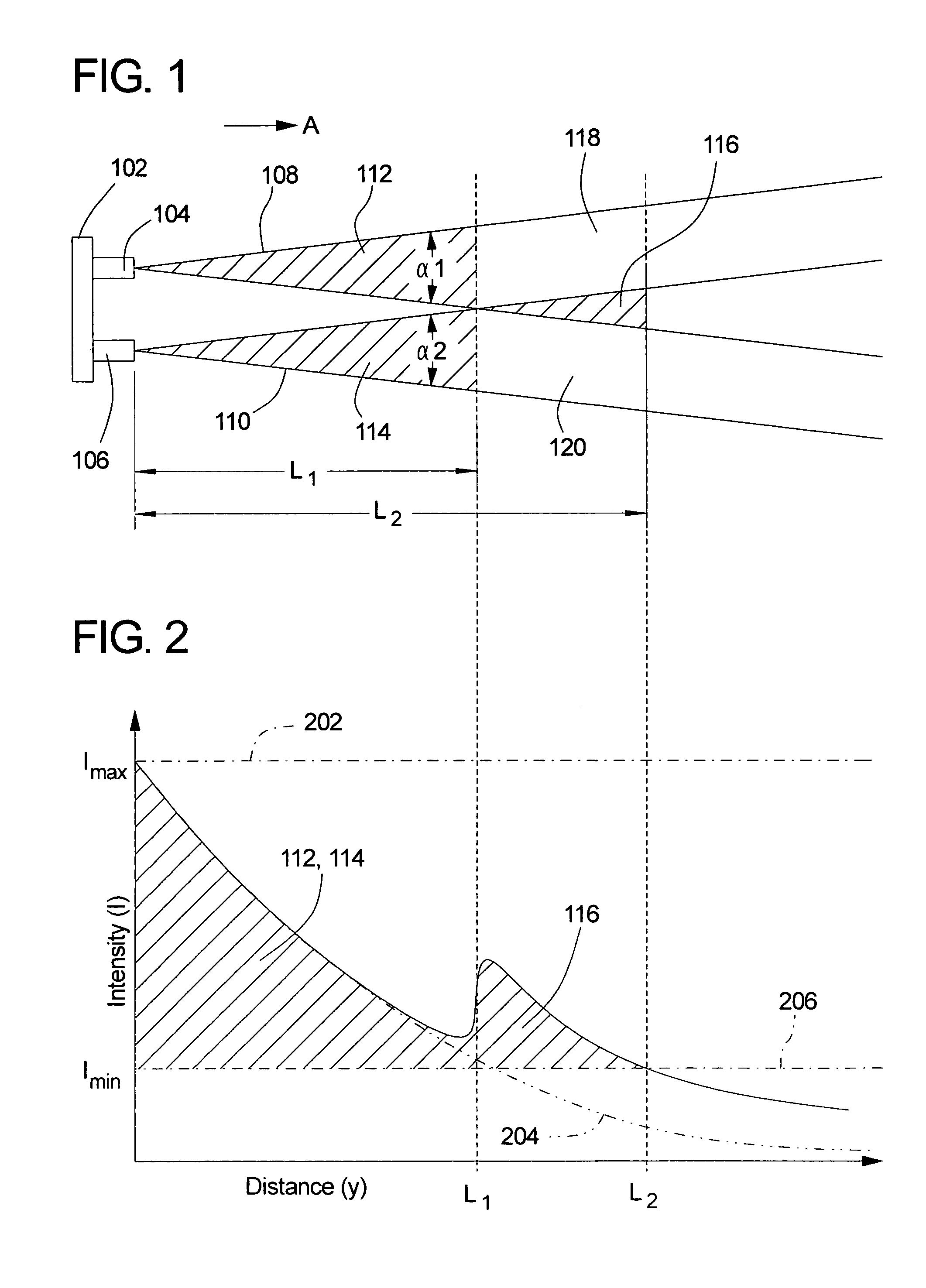
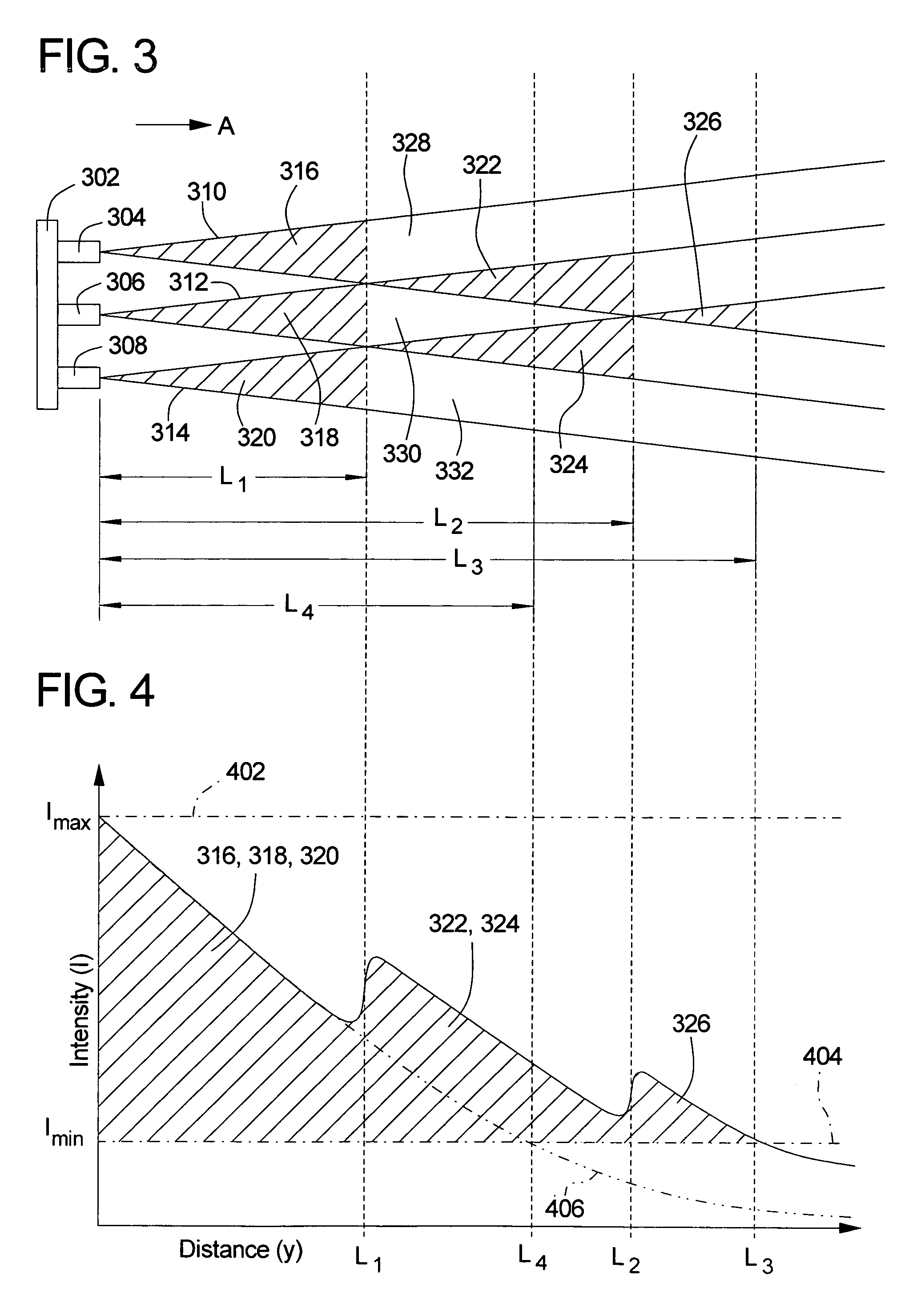
[0031]The present invention provides a multi-beam non-lethal laser weapon system for dazzling, flashblinding, illuminating or otherwise affecting an intended target subject. The system uses separate spaced-apart laser beams at close range, and uses the combined power densities of multiple overlapping beams at longer ranges to extend the effective range of the system. Generally speaking, the invention comprises a plurality of lasers that are rigidly mounted to a base that can be aimed by hand or by computer, remote and / or electronic control. The lasers include at least first and second lasers that are oriented to project respective laser beams generally along a first direction. Each of the first and second lasers diverge (i.e., grow in cross-sectional area) as they extend from the laser source, but are positioned so that they do not overlap one another until they reach a predetermined distance from the base. In the region before the laser beams overlap, they form two separate first-o...


PUM


Abstract

A non-lethal laser weapon having a base to which a number of lasers are mounted. The lasers include a first laser oriented to project a first laser beam in a first direction, and a second laser oriented to project a second laser beam generally in the first direction. The first laser beam and the second laser beam overlap at a first distance from the base, to thereby form separate first and second first-order illumination zones before the first distance, and a first second-order illumination zone beyond the first distance. Additional lasers may be included in one-, two-, and three-dimensional patterns to create additional illumination zones.

Description

CROSS-REFERENCE TO RELATED APPLICATIONS[0001]Not applicableBACKGROUND OF THE INVENTION[0002]1. Field of the Invention[0003]The present invention relates generally to laser systems and more particularly to non-lethal laser weapon systems for dazzling or stunning humans.[0004]2. Description of Related Art[0005]In recent years, military, security and police forces have placed an increasing emphasis on using non-lethal threat deterrence systems to neutralize threats without causing permanent injury to the target being suppressed. Such devices are desirable in a number of circumstances, such as when apprehending violent but unarmed subjects, for crowd control, during cell extractions, and when deadly force poses a risk to innocent bystanders or is otherwise unwarranted by the threat level. Examples of non-lethal weapons include high-voltage “taser” stun guns and chemical irritants such as pepper spray, tear gas, and the like.[0006]It has also been recognized that high-intensity light sou...

Claims


Application Information

Patent Timeline
Patent Type & Authority Patents(United States)
IPC IPC(8): G02B27/20F21L4/02F21V23/04F41H13/00H01S3/23
CPCF41H13/0081F41H13/0056
Inventor DIEHL, MATTHEW D.
Owner CHEMRING DETECTION SYST
Why Eureka
Try Eureka