

Golf ball and method of manufacturing the same
a manufacturing method and golf ball technology, applied in the field of golf balls, can solve the problems of reducing the degree of flexibility in the deformation of the cover, deteriorating the impact feel, etc., and achieve the effect of reliably preventing the eccentricity of the core and easy removal of the core from the core mould
- Summary
- Abstract
- Description
- Claims
- Application Information
AI Technical Summary
Benefits of technology
Problems solved by technology
Method used
Image

Examples
first embodiment
(First Embodiment)
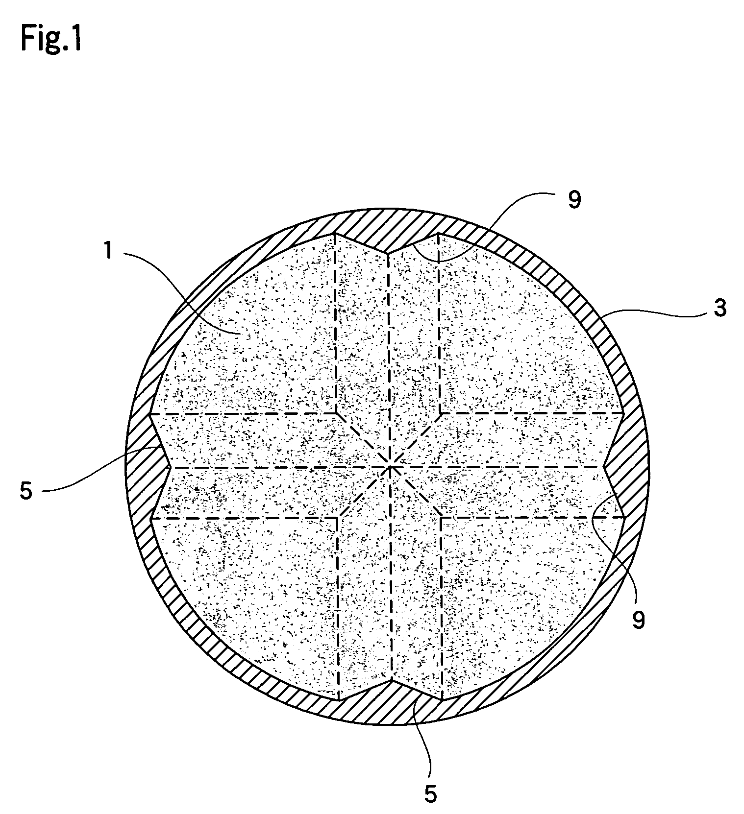
[0028]A first embodiment of a golf ball of the present invention is explained below. FIG. 1 is a cross-sectional view of a golf ball of the present invention.
[0029]As shown in FIG. 1, the golf ball of the present embodiment is a so-called two-piece golf ball comprising a core 1 and a cover 3 that covers the core 1. According to the rules (see R&A and USGA), the diameter of a golf ball should be no smaller than 42.67 mm. However, taking aerodynamic characteristics and the like into consideration, it is preferable that the diameter of the ball be as small as possible. Therefore, it can be, for example, 42.7 mm.
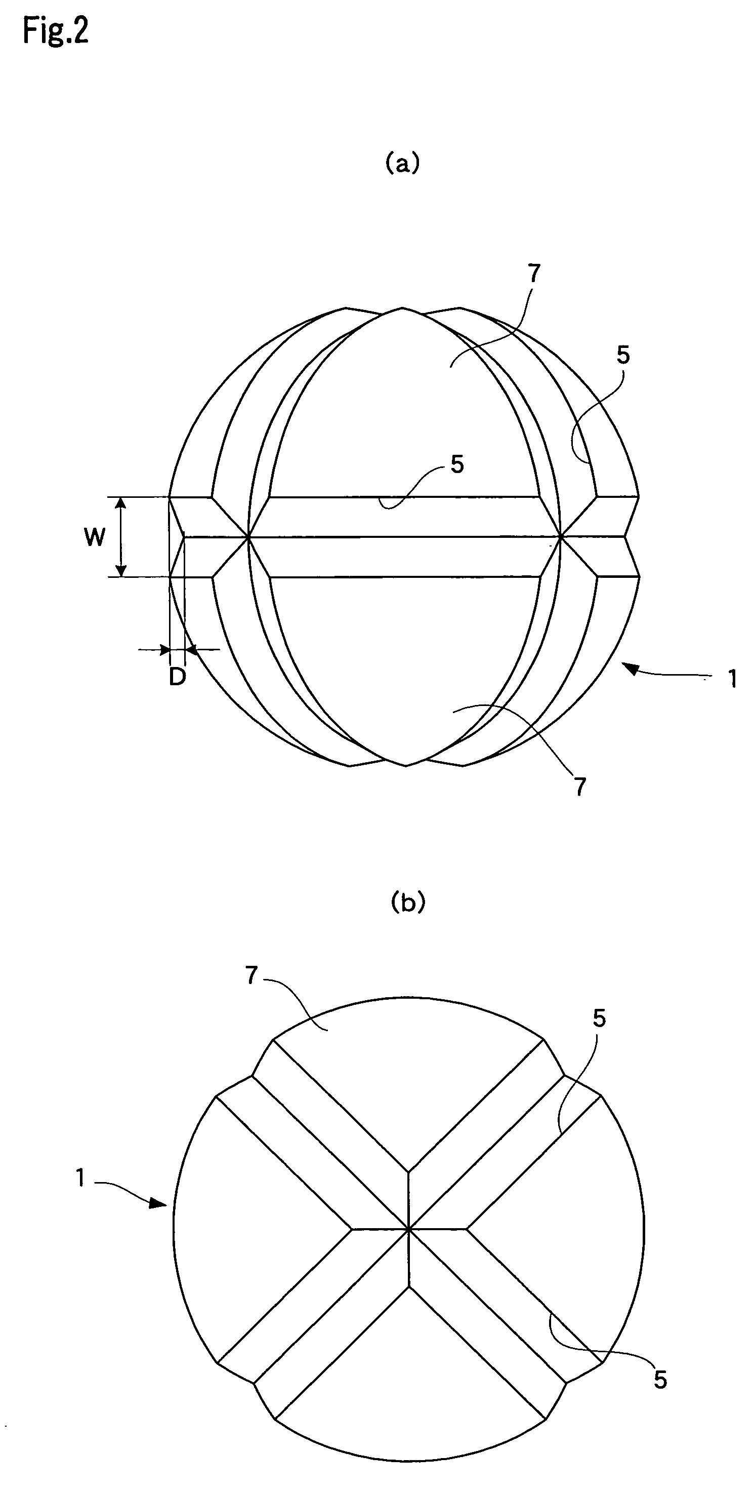
[0030]FIG. 2(a) is a front view of the core and FIG. 2(b) is a plan view of the core. The core 1 is spherically shaped as shown in the figures, and is composed of a rubber composition. It is preferable that the diameter of the core 1 be set in the range from 37.5 to 40.7 mm, and more preferably from 38.1 to 39.5 mm. This is because, when the diameter of the cor...
second embodiment
(Second Embodiment)
[0044]A second embodiment of the present invention is explained with reference to the drawings. FIG. 3 is a cross-sectional view of the golf ball of the present embodiment and FIG. 4 is (a) front view and (b) a side view of a core.
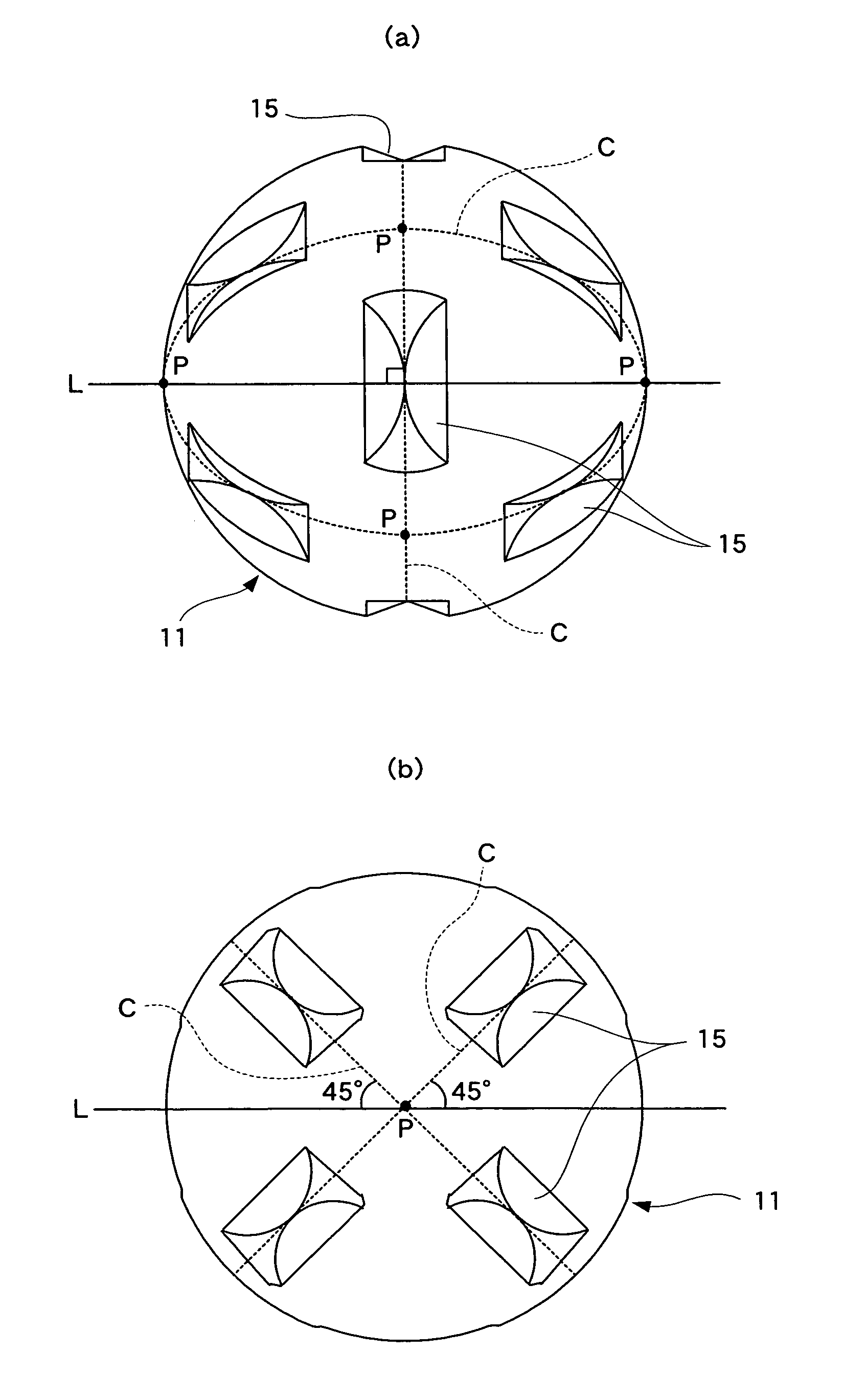
[0045]As shown in FIG. 3, the golf ball of the present embodiment is a two-piece golf ball comprising a core 11 and a cover 13 covering the core 11. As shown in FIG. 4, grooves 15 are formed on the surface of the core 11 of the golf ball as in the first embodiment. Each groove 15 extends along three great circles C drawn on the surface of the core 11 so as to intersect to each other at right angles; however the grooves 15 are not formed over the entire length of the great circles C but only some portions thereof. In other words, each grooves 15 is formed in a portion of each arc section between the intersections P of the great circles C, and the grooves 15 are not connected to each other.
[0046]To be more specific, each grooves 15 is form...
third embodiment
(Third Embodiment)
[0072]A third embodiment of the present invention is explained below. FIG. 10 is a cross-sectional view of a golf ball of the present embodiment. As with the golf balls of the above-explained embodiments, the golf ball of the present embodiment comprises a spherical core 21 having grooves 25 on its surface and a cover 23 that covers the core 21, wherein projections 29 engage in the grooves 25 are formed on the inner surface of the cover 23.
[0073]The golf ball of the present embodiment has a diameter and an outward form as the same as that of the second embodiment and is characterized in that the core 21 has a two-layered structure. In other words, the core 21 comprises a spherical main part 211 and an interlayer 212 that covers the surface of the main part 211, wherein the surface of the spherical interlayer 212 is provided with the grooves 25. Each groove 25 has the same shape as the grooves 15 of the second embodiment shown in FIG. 3 and a total of twelve grooves...
PUM
 Abstract
Description
Claims
Application Information