Micro-porous mesh stent with hybrid structure

a micro-porous mesh and hybrid structure technology, applied in the field of stents, can solve the problems of limited success in solving the problem of exposing the underlying wall of the treatment location, substantial harm, and reducing so as to facilitate endothelial growth and reduce the risk of embolic material releas

Inactive Publication Date: 2006-05-09
ENDOTEX INTERVENTIONAL SYST
View PDF23 Cites 80 Cited by
  • Summary
  • Abstract
  • Description
  • Claims
  • Application Information

AI Technical Summary

Benefits of technology

[0015]The tubular body may be heat treated at a first temperature substantially higher than the transition temperature to program an expanded condition for engaging the wall of the body passage into the shape memory material. The tubular body may then be cooled to a second temperature below the transition temperature, and compressed into a contracted condition for facilitating delivery into the body passage.
[0019]Thus, a prosthesis in accordance with the present invention may be used to treat a stenosis within a blood vessel, such as within the carotid, coronary or cerebral arteries. The tubular element may substantially trap embolic material against the wall of the vessel once secured by the support element, while the micro-porous mesh pattern facilitates endothelial growth, thereby substantially reducing the risk of releasing embolic material into the bloodstream. Also, the provision of a micro-porous mesh structure and a separate support structure may allow the support structure to slide along the surface of the tubular element without significantly disturbing the underlying diseased vessel wall.
[0020]In addition, in a preferred embodiment, the micro-porous mesh structure is biased to its enlarged condition such that the tubular body may tend to expand out to engage the vessel wall. Thus, the micro-porous mesh structure may contact the vessel wall at points between the struts of the support structure, thereby minimizing the creation of false lumens or other gaps between the micro-porous mesh structure and the vessel wall.

Problems solved by technology

One of the problems with many stent structures, whether balloon-expandable or self-expanding, is that they substantially expose the underlying wall of the treatment location.
Thus, despite holding the wall of the treatment location generally open, the openings or gaps in these stents may substantially expose the bloodstream to plaque, tissue prolapse, or other embolic material attached to the wall of the vessel.
This embolic material may be inadvertently released during or after deployment of the stent, and then travel downstream where it may cause substantial harm, particularly if it reaches a patient's neurovasculature.
This solution has met with limited success, however, because of the propensity to form false lumens due to poor apposition of the covering and the vessel wall.

Method used


Image

  • Micro-porous mesh stent with hybrid structure
  • Micro-porous mesh stent with hybrid structure
  • Micro-porous mesh stent with hybrid structure

Examples


Embodiment Construction

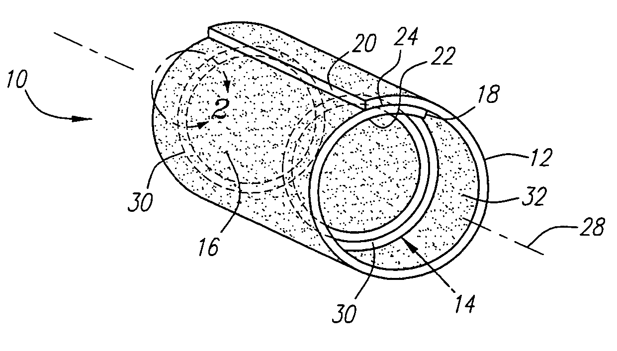
[0028]Turning now to the drawings, FIG. 1 shows a first preferred embodiment of a stent 10 in accordance with the present invention. Generally, the stent 10 includes two elements, namely a micro-porous tubular element 12 and a support element 14. Both elements 12, 14 have a contracted condition for facilitating introduction into a body passage, such as a patient's vasculature, and an enlarged condition for engaging the wall of a treatment location, such as a stenotic region of a blood vessel.

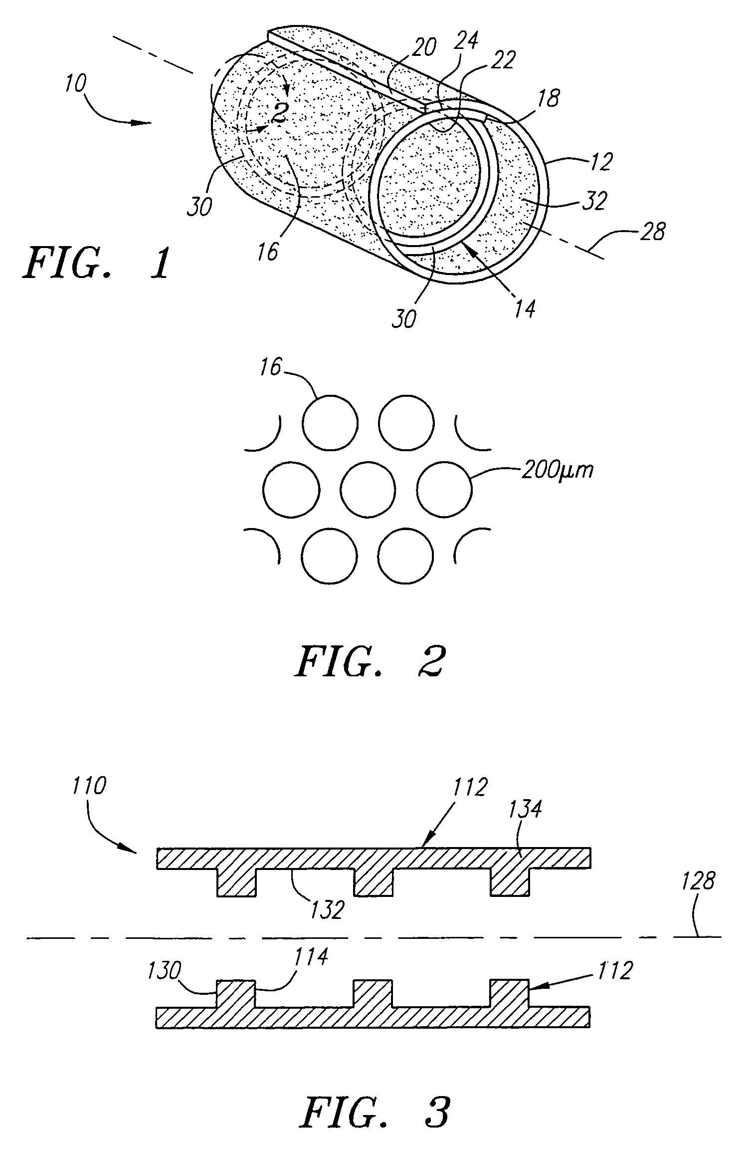
[0029]The micro-porous tubular element 12 is preferably formed from a shape memory alloy, such as Nitinol, having a plurality of openings 16 defining a micro-porous mesh pattern therein. The mesh pattern is “micro-porous” in that the openings 16 are sufficiently small such that they substantially prevent plaque or other embolic material from extending through the openings 16. Thus, the tubular element 12 may behave as a filter, allowing endothelial growth to occur through the openings 16 while s...


PUM


Abstract

A prosthesis for treating a body passage includes a micro-porous tubular element and a support element. The tubular element is formed from a thin-walled sheet having a wall thickness of 25 micrometers or less, preferably a coiled-sheet exhibiting temperature-activated shape memory properties. The mesh pattern includes a plurality of openings in the sheet having a maximum dimension of not more than about 200 micrometers, thereby acting as a filter trapping embolic material while facilitating endothelial growth therethrough. The support element includes a plurality of struts, preferably having a thickness of 100–150 micrometers. The support element is preferably an independent component from the tubular element. Alternatively, the support element may be attached to or integrally formed as part of the tubular element. The tubular and support elements are placed on a catheter in contracted conditions and advanced endoluminally to a treatment location within a body passage. The tubular element is deployed, and the support element is expanded to an enlarged condition at the treatment location to engage an interior surface of the tubular element, thereby securing the tubular element and holding the lumen of the treatment location open.

Description

RELATED INFORMATION[0001]This application is a continuation of application Ser. No. 09 / 929,474, filed Aug. 13, 2001, now U.S. Pat. No. 6,676,701, which is a continuation of application Ser. No. 09 / 495,827, filed Feb. 1, 2000, now U.S. Pat. No. 6,312,463, the disclosure of which is expressly incorporated herein by reference.FIELD OF THE INVENTION[0002]The present invention relates generally to endoluminal prostheses or “stents,” and more particularly to stents including a micro-porous mesh structure supported by an integral or separate strut structure, and to methods of making and deploying such stents.BACKGROUND[0003]Tubular prostheses or “stents” are often implanted within blood vessels, for example, within the coronary and carotid arteries, for treating atherosclerotic disease that may involve one or more stenoses. Stents generally have a tubular shape capable of assuming a radially contracted condition to facilitate introduction into a patient's vasculature, and an enlarged condi...

Claims


Application Information

Patent Timeline
Patent Type & Authority Patents(United States)
IPC IPC(8): A61F2/04A61F2/00A61F2/01A61F2/90A61F2/92
CPCA61F2/01A61F2/90A61F2/91A61F2/92A61F2/856A61F2220/0058A61F2230/0069A61F2002/018A61F2230/0006A61F2220/005A61F2210/0019
Inventor ROURKE, JONATHAN M.YANG, YI
Owner ENDOTEX INTERVENTIONAL SYST
Why Eureka
Try Eureka