Image forming apparatus

a technology of forming apparatus and forming tube, which is applied in the direction of electrographic process apparatus, instruments, optics, etc., can solve the problems of affecting the maintenance of the device, affecting the maintenance efficiency of the device, so as to improve the maintenance ease

Inactive Publication Date: 2006-05-09
KONICA MINOLTA BUSINESS TECH INC
View PDF2 Cites 24 Cited by
  • Summary
  • Abstract
  • Description
  • Claims
  • Application Information

AI Technical Summary

Benefits of technology

[0005]An embodiment of the present invention provide an image forming apparatus having therein a developing means in which the above drawbacks are overcome, that is, the scattered developers do not block up the air vent of the air duct of the scattered developer suction means, and further the air duct and air vent are easily cleaned, and maintenance work is easily performed.
[0007]Since the present invention may be structured like above, the present invention may comprise an image forming apparatus, which may improve the condition that the scattered developers do not block up the air vent of the air duct of the scattered developer suction means, and thereby, it is very easy to clean the scattered developer suction means, the air duct and air vent, and also proposes an image forming apparatus having therein the developing means featured improved maintenance ease.

Problems solved by technology

Specifically, regarding the higher durability of the developer, the big problem is scattering of the developer.
However, in the image forming apparatus providing the above-mentioned developing means, the developers scattered from the developing means accumulate in the air duct of the scattered developer suction means, and the air vent is blocked, requiring periodic cleaning.
Further, when the user cleans the scattered developer suction means installed in the developing means or its air duct, it is very difficult for the user to make clean them, because the air duct is very thin.

Method used


Image

  • Image forming apparatus
  • Image forming apparatus
  • Image forming apparatus

Examples


Embodiment Construction

[0012]Embodiment of the present invention will be explained in detail below. The description in this embodiment does not limit the technical scope of the claims nor the meaning of terms. Further the assertive explanation in the embodiment of the present invention shows the best condition, but does not limit the technical scope nor the meaning of terms in the present invention.

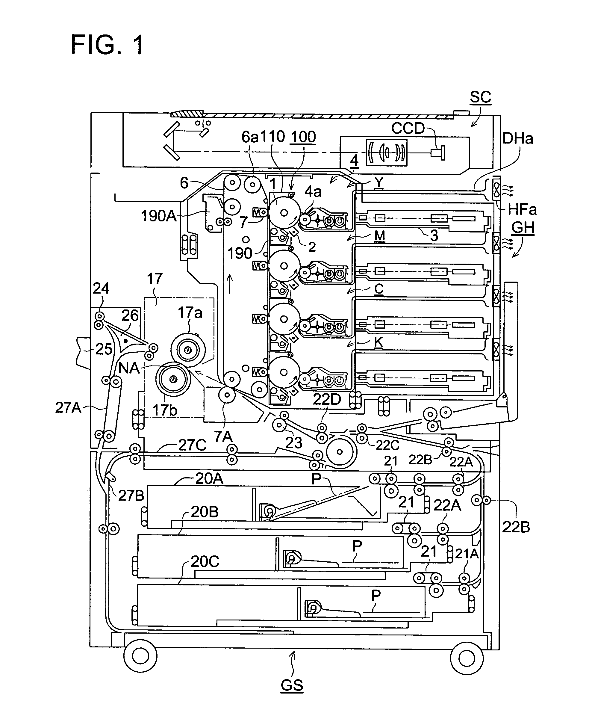
[0013]The image forming apparatus provided with the developing means relating to the present invention will be described as follows, while referring to FIG. 1.

[0014]In FIG. 1, image forming apparatus GS is structured by image forming apparatus main body GH, and image reading device SC mounted on image forming device main body GH.

[0015]Image forming apparatus main body GH is called a tandem type color image forming apparatus, wherein image forming units for forming color toner images of yellow, magenta, cyan and black are arranged for sequential conveyance in an intermediate transfer body, and wherein color tone...


PUM


Abstract

An image forming apparatus may comprisea suction section, fitted onto the air vent, for sucking toner particles scattered in the image forming apparatus, includingan intermediate duct in which the toner particles accumulate and which is detachable from the suction section, andan exhaust fan for sucking air including the toner particles, through the intermediate air duct, and discharging air outside the image forming apparatus.

Description

BACKGROUND OF THE INVENTION[0001]The present invention relates to an image forming apparatus having therein a developing means which can be installed in a copying machine, printer or facsimile, each of which use an electronic photographic method.[0002]In recent years, in the field of electronic photography, required is higher durability of a developer (which is toner), and a longer maintenance cycle. Specifically, regarding the higher durability of the developer, the big problem is scattering of the developer.[0003]Developers having a lower amount of electrical charge, are scattered by the rotation of developer carrier (which is a developing sleeve), which faces the image carrier (which is a photoconductor drum), from the downstream of the developer carrier with respect to the rotating direction of the developer carrier. As a counter measure for the above problem, proposed is a developing means wherein an air vent of an air duct of a scattered developer suction means is formed as de...

Claims


Application Information

Patent Timeline
Patent Type & Authority Patents(United States)
IPC IPC(8): G03G21/00G03G15/08
CPCG03G15/0898G03G21/0052G03G2221/0005
Inventor KOSHIMURA, YASUSHIKOISO, JUNICHIWATANABE, KANEHIRO
Owner KONICA MINOLTA BUSINESS TECH INC
Why Eureka
Try Eureka