
Fastening system

a technology of fastening system and fastening means, applied in the direction of threaded fasteners, fastening means, nails, etc., to achieve the effect of economic manufacturing and simple assembly

Inactive Publication Date: 2006-05-16
HILTI AG
View PDF18 Cites 70 Cited by
  • Summary
  • Abstract
  • Description
  • Claims
  • Application Information

AI Technical Summary

Benefits of technology

[0007]The object of the present invention is to provide a fastening system having a rotatable rear grip part, which makes it possible to pre-fix the fastening system to a hollow body without a rotaton about a specific angle, wherein a correct positioning of the rear grip part is secured with the mounting projections. Further, the fastening system can be economically manufactured and allow simple assembly.

Problems solved by technology

The drawback of the known solution is that the anchoring unit must be further rotated after introduction through the mounting opening of the mounting rail by a specific angle, in order to optimally grip the mounting projections.
Especially at difficult to access locations, this circumstance is a drawback when mounting the anchoring unit.

Method used


Image

  • Fastening system
  • Fastening system
  • Fastening system

Examples


Embodiment Construction

[0034]In principle, in the figures identical parts are identified using identical reference numerals.

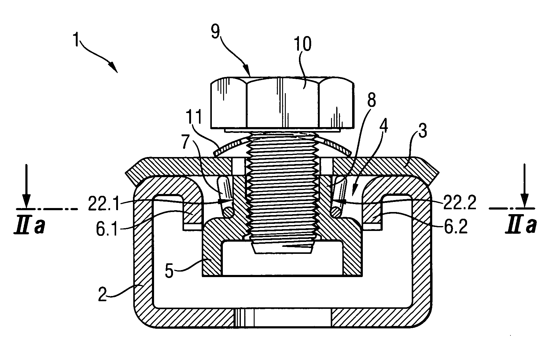
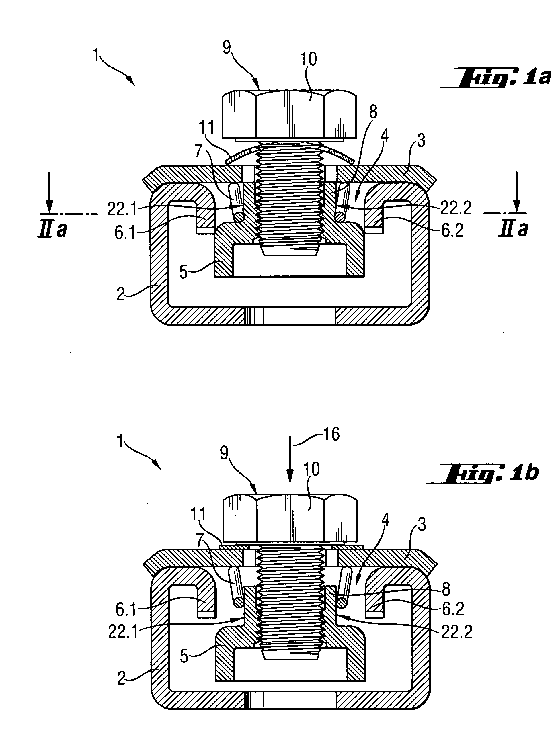
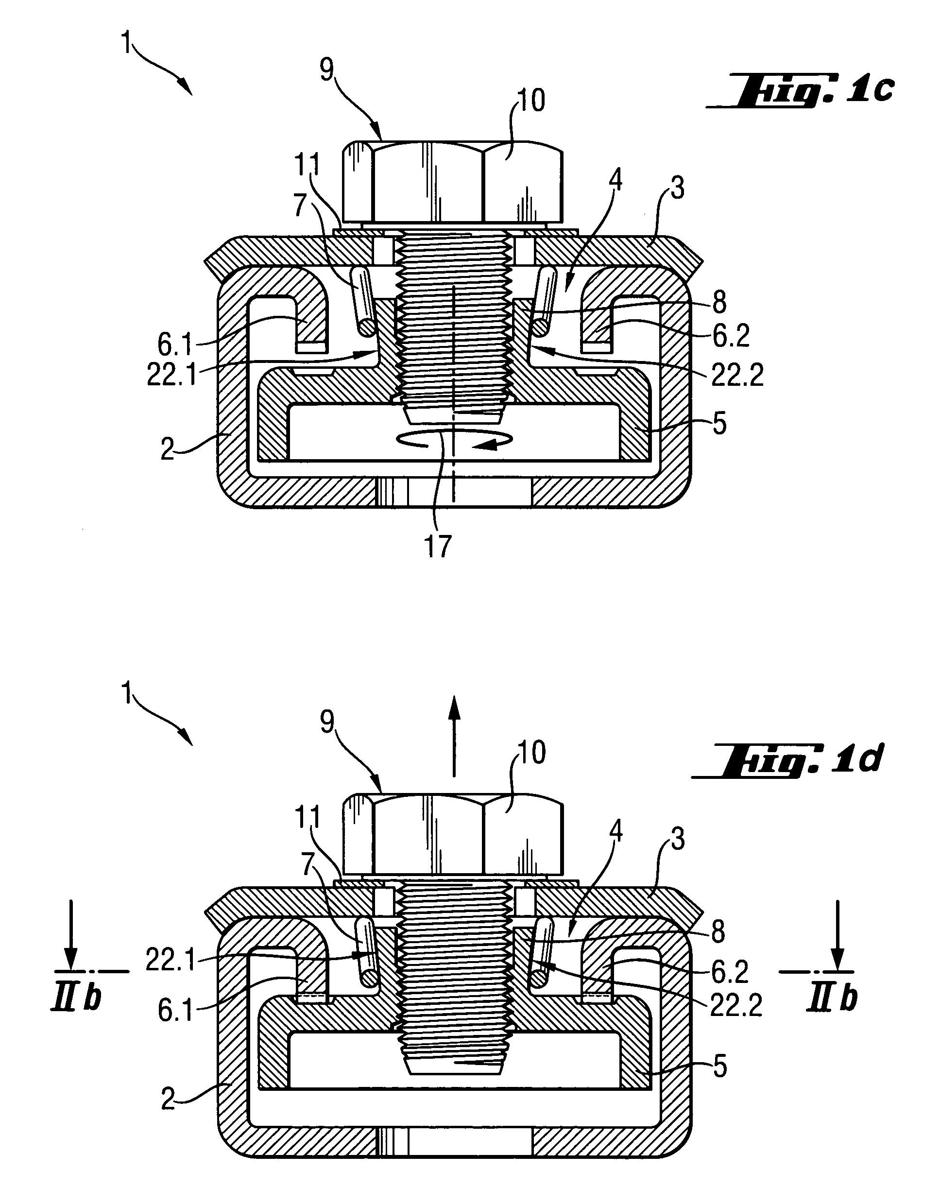
[0035]FIGS. 1a–d represents a first exemplary embodiment of the fastening system according to the invention in four individual steps of the setting operation. The fastening system 1 is represented in FIG. 1a after introduction into an elongated hollow body 2 shaped as a mounting rail. The stop 3 bears on the edges adjacent to the mounting opening, on the hollow body 2 shaped as a mounting rail. In this position the distance between the rear grip part 5 and the stop 3 is inadequate so that the rear grip part 5 cannot be rotated under the mounting projections 6.1 and 6.2 in this position.

[0036]A spring clip is provided as the spring-loaded element 7 between the stop 3 and the rear grip part 5, the element engaging in two diametrically opposed slotted members 22.1, 22.2 arranged on the shaft 8. The interplay between the spring clip and the slotted member(s) 22.1, 22.2 is described in de...


PUM


Abstract

A fastening system (1) comprises a rear grip part (5) for introduction into a mounting opening (4) of an elongated mounting rail (2) in a first position and for gripping behind the mounting projections (6.1, 6.2) in a second position and a stop (3) for frontal external loading of the mounting rail (2). The stop (3) is connected to the rear grip part (5) by means of a threaded bolt (9). In addition, on the fastening system (1) a system is provided for providing a relative rotary movement between the stop (3) and the rear grip part (5) about the axis of the bolt (9). The system is configured as a transmission system for transforming a translatory movement of the bolt (9) relative to the stop (3) into a rotary movement of the rear grip part (5) relative to the stop (3).

Description

BACKGROUND OF THE INVENTION[0001]1. Technical Field[0002]The invention relates to a fastening system with a rear grip element for introduction in a first position into a mounting opening of a elongated hollow body and in a second position for rear gripping mounting projections arranged in the hollow body, as well as having at least one stop for frontal external contact of the edges abutting the hollow body longitudinal walls. The stop is connected with the rear grip element by means of a fastening element. A device for introducing a relative rotary movement is provided between the stop and the rear grip element about the axis of the fastening elements.[0003]2. Description of the Prior Art[0004]Fastening systems of the above type are known for fastening of an object, for example, to C-shaped mounting rail fixed to a surface. The fastening system is introduced into the mounting opening of the mounting rail and rotated, for example, by an angle of 90°. When this is done the rear grip p...

Claims


Application Information

Patent Timeline
IPC IPC(8): F16B27/00F16B21/00F16B37/04
CPCF16B37/046
Inventor HERB, ARMIN
Owner HILTI AG
Features
  • Generate Ideas
  • Intellectual Property
  • Life Sciences
  • Materials
  • Tech Scout
  • Unparalleled Data Quality
  • Higher Quality Content
  • 60% Fewer Hallucinations
Learn More