
Fracture fixation device in which a fixation pin is axially restrained

a fixation device and fracture technology, applied in the field of fracture fixation devices, can solve the problems of abrasion of adjacent soft tissue structures, k-wire fixation of single bone fragments that does not provide secure fixation, and can lose reduction, so as to prevent the translational movement of the k-wire, simplify the procedure, and prevent the effect of k-wire backing out of the soft tissu

Inactive Publication Date: 2006-05-16
MEDOFF ROBERT J +2
View PDF7 Cites 42 Cited by
  • Summary
  • Abstract
  • Description
  • Claims
  • Application Information

AI Technical Summary

Benefits of technology

[0008]A further object of the invention is to secure the top of the protruding end of the K-wire to prevent translational movement of the K-wire as well as to prevent backing out of the wire into the soft tissues.
[0009]Another object of the invention is to provide a bend in the K-wire prior to placement of the fixation plate so that the K-wire need not be withdrawn from the bone, simplifying the procedure.
[0010]In accordance with the above and further objects of the invention, the fixation device for fixing a fracture in a bone structure comprises a fixation pin adapted for penetrating through an unstable bone fragment of the bone structure across a fracture into a stable bone fragment, the pin having one end secured to the stable bone fragment and an opposite end extending out from the unstable bone fragment, and a fixation plate adapted for being secured to the stable bone fragment at a distance from the outwardly extending end of the fixation pin. The outwardly extending end of the fixation pin is smooth and the fixation plate is engageable with the end of the pin to prevent the pin from backing out of the unstable bone fragment while providing restraint against movement of the pin in the plane of the plate.

Problems solved by technology

Single K-wire fixation of bone fragments does not provide secure fixation, since the K-wire is secured only at a single end that can be at a considerable distance from the fracture site.
The fixation or pin plate provides fixation of the K-wire at a second site, but has the disadvantage of requiring the K-wire to be bent over the edge of the plate or into an adjacent hole in the plate.
This step requires backing out of the K-wire and is cumbersome and can lose reduction.
This can lead to abrasion of adjacent soft tissue structures and even tendon rupture.

Method used


Image

  • Fracture fixation device in which a fixation pin is axially restrained
  • Fracture fixation device in which a fixation pin is axially restrained
  • Fracture fixation device in which a fixation pin is axially restrained

Examples


Embodiment Construction

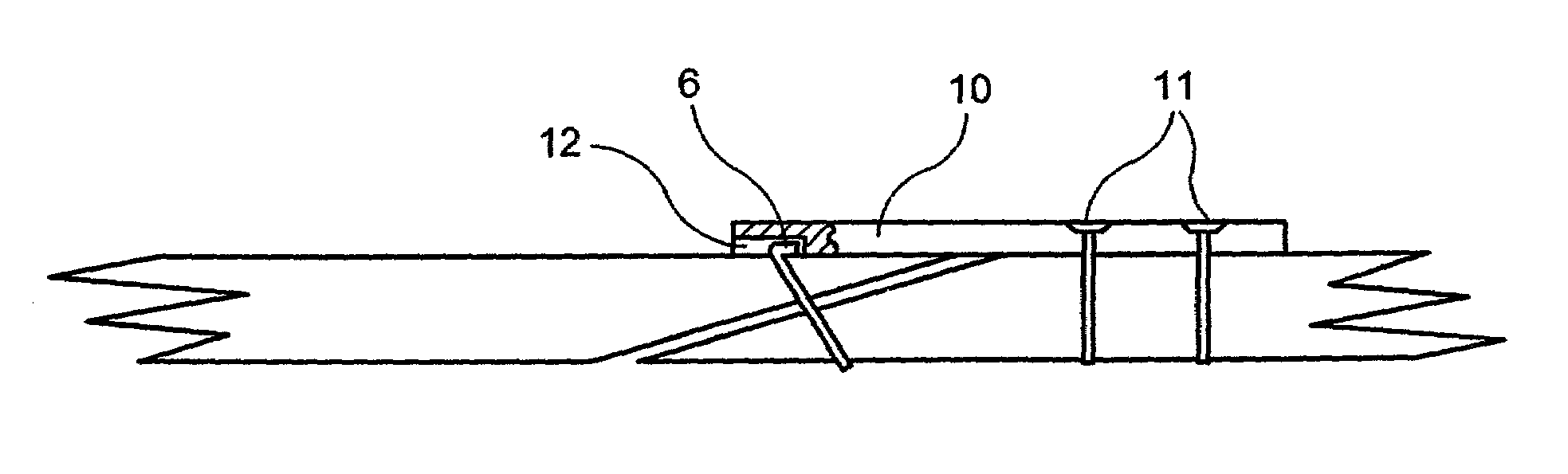
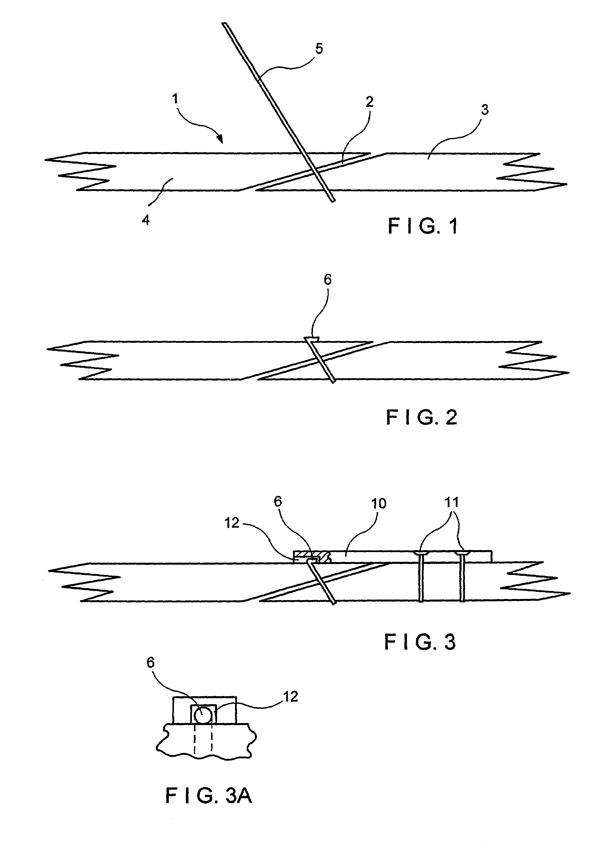
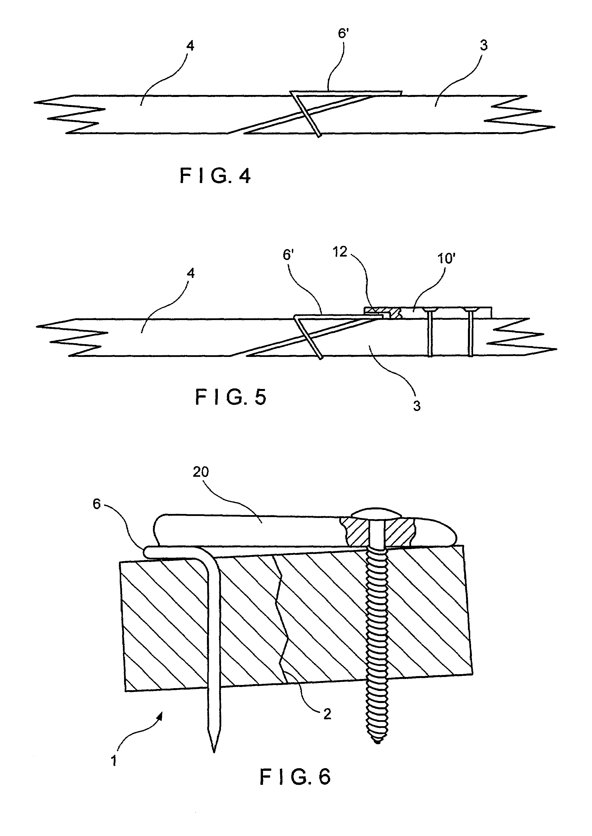
[0056]Referring to FIG. 1 therein is seen a bone structure 1 having a fracture 2 therein forming a stable bone fragment 3 and an unstable bone fragment 4 on opposite sides of the fracture 2. In order to provide fixation of the unstable bone fragment 4 to the stable bone fragment 3, a K-wire or pin 5 is inserted through the unstable bone fragment 4 across the fracture 2 into the stable bone fragment 3. The end of the pin 5 which engages in the stable bone fragment 3 can be smooth or threaded to insure its anchorage in the stable bone fragment. After the pin 5 has been secured in the bone structure and the fracture 2 has been reduced, the part of the pin 5 extending from the anterior surface of the bone structure is severed and bent to form a bent portion 6. The bent portion 6 is bent at an angle so that the bent portion 6 will be substantially parallel to the superficial surface of the bone structure 1 and be capable of engagement thereon as shown in FIG. 2. In order to secure the pr...


PUM


Abstract

A fixation device for fixing a fracture in a bone structure, in which a fixation pin adapted for penetrating into a stable fragment of a bone structure across a fracture has an end extending from an unstable fragment of the bone structure and a fixation plate adapted for being secured to the stable bone fragment distally from the end of the fixation pin. The fixation plate is engageable with the end of the pin to prevent the pin from backing out of the unstable bone fragment while providing restraint against movement of the pin in the plane of the plate. The end of the pin extending from the unstable bone fragment is engaged an opening in the end of the fixation plate and restrained thereat.

Description

[0001]This application claims the benefit of Provisional Application No. 60 / 268,100, filed Feb. 12, 2001.FIELD OF THE INVENTION[0002]The invention relates to a fixation device for fixing a fracture in a bone structure and more particularly to a fixation pin for penetrating an unstable bone fragment for being secured to a stable bone fragment, the pin having an end which extends out of the bone structure and is restrained by a fixation plate.[0003]The invention also relates to a method of fixing a bone fracture utilizing such a pin and plate.BACKGROUND AND PRIOR ART[0004]In my earlier U.S. Pat. No. 5,931,839, there is disclosed an implantable fixation device which comprises a K-wire or pin for fixation of a bone fracture and a fixation plate for engaging the end of the pin which extends from the bone structure. In the patent, the protruding end of the pin is engaged in a hole in the fixation plate such that the pin is free to axially travel in the hole. In order to prevent separation...

Claims


Application Information

Patent Timeline
Patent Type & Authority Patents(United States)
IPC IPC(8): A61B17/56A61B17/58A61B17/80A61B17/84
CPCA61B17/80A61B17/8052A61B17/842
Inventor MEDOFF, ROBERT J.TELLMAN, LARS G.
Owner MEDOFF ROBERT J
Features
  • Generate Ideas
  • Intellectual Property
  • Life Sciences
  • Materials
  • Tech Scout
  • Unparalleled Data Quality
  • Higher Quality Content
  • 60% Fewer Hallucinations
Learn More