Fixture

a technology of fixing and fixing state, applied in the field of fixing, can solve the problems of reducing detachment operation, reducing the retentivity of the attachment state, so as to improve the workability of the attachment operation and prevent improper cancellation of the attachment state. , the effect of easy attachment and detachmen

Inactive Publication Date: 2006-05-16
YASUNORI MASATOSHI
View PDF2 Cites 34 Cited by
  • Summary
  • Abstract
  • Description
  • Claims
  • Application Information

AI Technical Summary

Benefits of technology

[0012]In the case where the fixture is detached from the attachment target section, a player or a user presses the operation portion of the engagement member inward so as to rotate the engagement member against the biasing force of the biasing member. Consequently, the engagement portion projected inside the insertion groove are moved to the outside, which brings the insertion groove and the through hole in a linked state. In this state, the fixture is slid along the extension direction of the insertion groove in the direction opposite to that in the attachment operation, so that the shaft portion of the attachment target section is positioned in the through hole, thereby allowing easy detachment of the fixture from the attachment target section.
[0013]Thus, the fixture of the present invention can be easily attached and detached to / from attachment objects via the attachment target section. Moreover, the attachment state where the fixture is attached to the attachment target section can be reliably retained because the small hole formed by the engagement portion and the end portion of the insertion groove is larger than the shaft portion of the attachment target section and smaller than the bulging portion of the attachment target section.
[0014]In the above-described fixture, in the state of being projected inside the insertion groove of the main body, the engagement portion of the engagement member should preferably form a large hole larger than the bulging portion of the attachment target section along with the through hole. This makes it possible to further improve the workability of the attaching operation.
[0015]Further, it is preferable that the main body is composed of a pair of plate-like members, and the engagement member and the biasing member are disposed so as to be interposed therebetween. Consequently, it becomes possible to thoroughly prevent improper cancellation of the attachment state due to interference between the engagement member and the attachment target section.

Problems solved by technology

However, in the above-mentioned attachment structure, there is a problem that if the strip-shaped member is made from a hard material, the workability with respect to attaching and detaching operations is deteriorated although the retentivity to retain the attachment state is increased.
Further, there is a problem that if the strip-shaped member is made from a soft material, the workability with respect to attaching and detaching operations is improved, although the retentivity to retain the attachment state is weakened.
Thus, if the retentivity of the attachment state is weak, the strap 3 possibly comes loose from the attachment target sections 2, thereby causing an expensive guitar 1 to be dropped off.
However, the above-mentioned fixture member still has problems that the workability of the attaching operation is deteriorated depending on the projection amount and the material of the engagement piece, and that the retentivity for retaining the attachment state is weakened.

Method used


Image

  • Fixture
  • Fixture
  • Fixture

Examples


Embodiment Construction

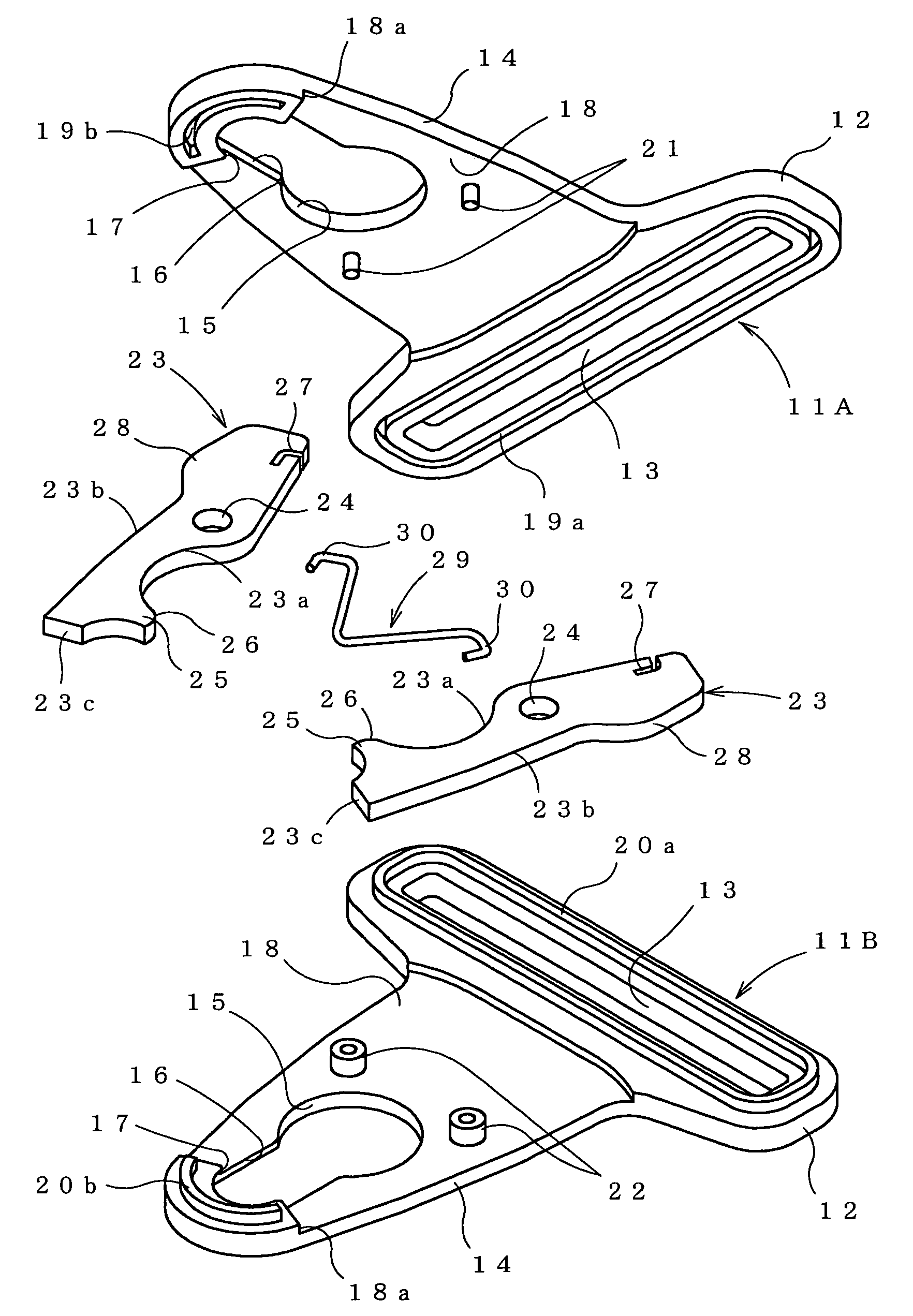
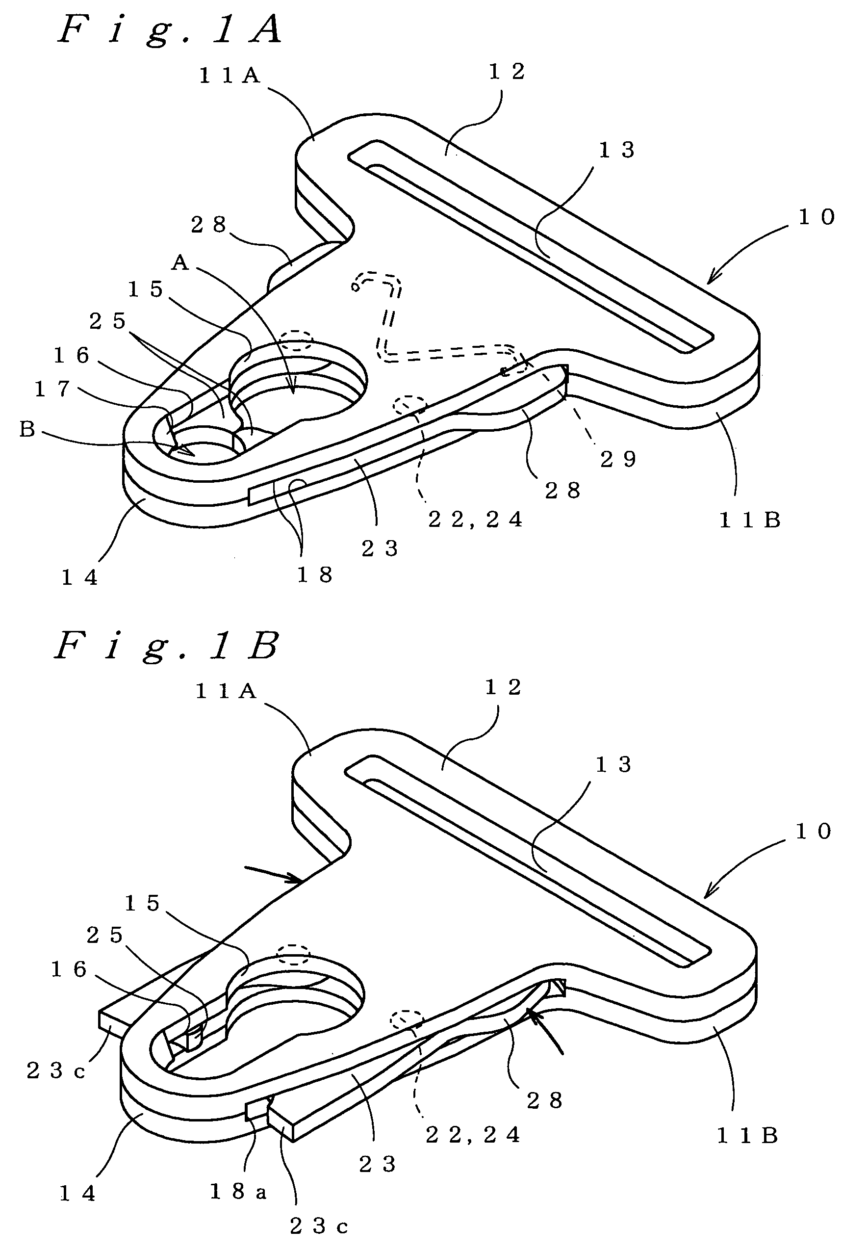
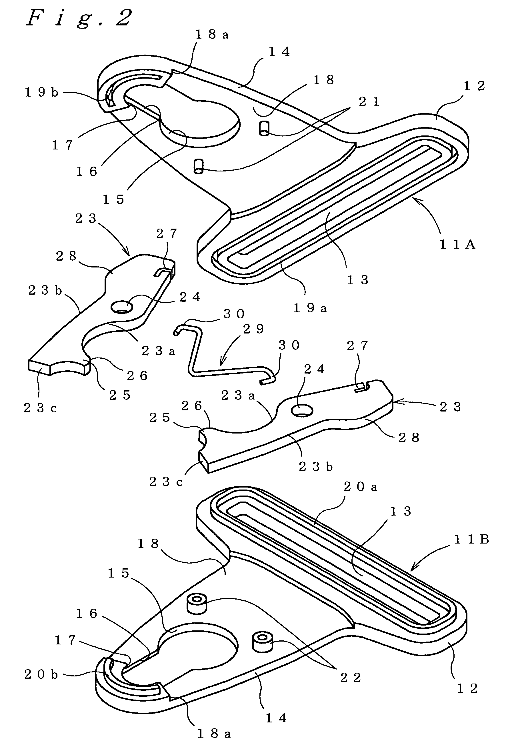
[0025]FIGS. 1A, 1B and FIG. 2 show a fixture in an embodiment of the present invention. This fixture is mainly composed of a main body 10, a pair of engagement members 23 that are rotatably mounted on the main body 10, and a biasing member 29 for biasing the engagement members 23.

[0026]The main body 10 is composed of a pair of plate-like members 11A and 11B, and the engagement members 23 and the biasing member 29 are disposed so as to be interposed therebetween. More specifically, the plate-like members 11A, 11B are almost T shaped members, each of which is composed of a wide-width placement portion 12 in which a strap 3 or a strip-shaped member is placed, and a narrow-width attachment portion 14 projected from the placement portion 12 so as to form an approximate triangle. These plate-like members 11A, 11B are formed such that in the state of being assembled so as to face each other, their thickness is smaller than a total height T of the attachment target section 2. The total heig...


PUM


Abstract

A fixture is made up of: a made body 10 composed of a placement portion 12 in which a stripe-shaped member (strap 3) or a line-shaped member is inserted and placed, a through hole 15 through which a bulging portion 2b of an attachment target section 2 can be inserted, and an insertion groove 16 linked to the through hole 15 and extended from the through hole 15 to an opposite side of the placement portion 12 in which the shaft portion 2a of the attachment target section 2 is inserted; engagement members 23 that are rotatably mounted on the main body 10 and that are composed of engagement portions 25 projected inside the insertion groove 16 to form a small hole B larger than the shaft portion 2a and smaller than a bulging portion 2b along with an end portion of the insertion groove 16, and operation portions 28 projected outward from the main body 10: and a biasing member 29 for biasing the engagement members 23 so as to retain the engagement portions 25 of the engagement members 23 in a state of being projected inside the insertion groove 16 of the main body 10. A fixture including: a main body composed of a placement portion in which a stripe-shaped member or a line-shaped member is inserted and placed, a through hole through which a bulging portion of an attachment target section can be inserted, and an insertion groove linked to the through hole and extended from the through hole to an opposite side of the placement portion, in which the shaft portion of the attachment target section is inserted; engagement members that are rotatably mounted on the main body and that are composed of engagement portions projected inside the insertion groove to form a small hole B larger than the shaft portion and smaller than a bulging portion along with an end portion of the insertion groove, and operation portions projected outward from the main body; and a biasing member for biasing the engagement members.

Description

[0001]This nonprovisional application claims priority under 35 U.S.C. § 119(a) on Patent Application No. 2002-349730 filed in JAPAN on Dec. 2, 2002, the entire contents of which are hereby incorporated by reference.BACKGROUND OF THE INVENTION[0002]The present invention relates to a fixture for attaching strip-shaped members such as straps to guitars that are attachment objects.[0003]As shown in FIG. 7, on a guitar 1, that is one of the attachment objects to which a strip-shaped member is attached, there are fixed attachment target sections 2 on the both back and front ends of its main body. When a player stands up and plays the guitar, he / she attaches a strap 3 to the attachment target sections 2 and has the strap 3 over his / her shoulder to hold the guitar 1 in place.[0004]As shown in FIGS. 8A and 8B, the attachment target section 2, which is almost T-shaped at cross section, is composed of a shaft portion 2a having a circular cross section and a bulging portion 2b projected onward ...

Claims


Application Information

Patent Timeline
Patent Type & Authority Patents(United States)
IPC IPC(8): G10D3/00F16B1/00A44B11/25F16B1/02F16B2/20F16B21/09F16B45/00G10D3/18G10G5/00
CPCA44B11/2584G10G5/005Y10T24/45623
Inventor YASUNORI, MASATOSHI
Owner YASUNORI MASATOSHI
Why Eureka
Try Eureka