

Analog-to-digital converter with range error detection
an analog-to-digital converter and range error technology, applied in the field of analog-to-digital converters with range error detection, can solve the problems of process control systems that malfunction without adequate warning,
- Summary
- Abstract
- Description
- Claims
- Application Information
AI Technical Summary
Problems solved by technology
Method used
Image

Examples
first embodiment
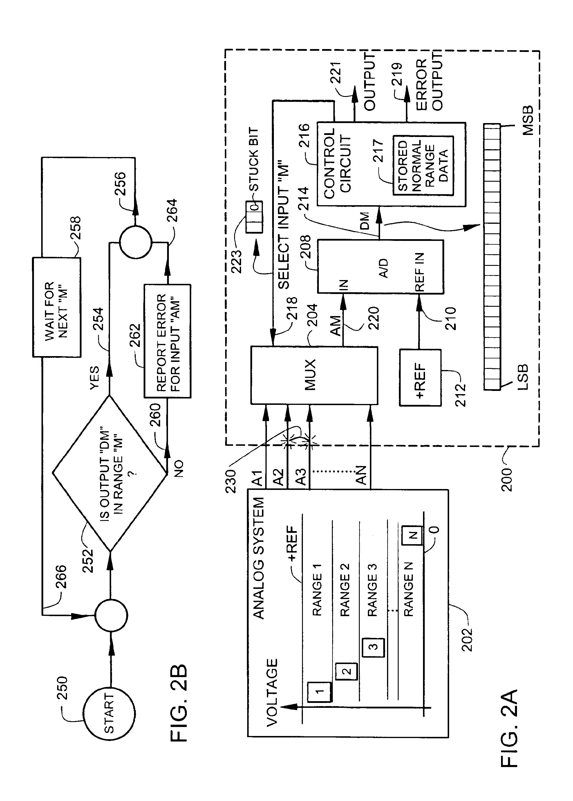
[0025]FIG. 2A illustrates an circuit 200 with a dynamically changing input range and an error output 219. The circuit 200 is typically used to process analog variables in an industrial process variable transmitter such as the transmitter illustrated in FIG. 7, but can be used in a wide variety of other applications using multiplexed analog-to-digital conversion.
[0026]The circuit 200 receives a plurality of analog inputs A1, A2, A3, . . . AN from an analog system 202. Each analog input has a normal operating range (RANGE 1, RANGE 2, RANGE 3, . . . RANGE N) associated with it. The analog system 202 has been specially configured so that each analog input has a normal operating range that is different from the normal operating range of the other remaining analog inputs. In a preferred embodiment, the normal operating ranges of the analog inputs are non-overlapping. In a typical analog system 202, the analog inputs are conditioned by a combination of scaling, inversion or level shifting ...
second embodiment
[0036]FIG. 3A illustrates a circuit 300 with a dynamically changing input range and an error output 219. Reference numbers used in FIG. 3A that are the same as reference numbers used in FIG. 2A designate the same or similar features.
[0037]The circuit 300 receives a plurality of analog inputs A1, A2, A3, . . . AN from an analog system 302. Each analog input has a normal operating range (RANGE 1, RANGE 2, RANGE 3, . . . RANGE N) associated with it. The analog system 302 has been specially configured so that odd-numbered analog inputs (A1, A3, . . . ) are in an odd normal operating range, and even-numbered analog inputs (A2, A4, . . . ) are in an even normal operating range. In a preferred embodiment, the odd and even operating ranges of the analog inputs are non-overlapping and each of the two operating ranges extends over about one half of the input range of the A / D 208. In another preferred arrangement, there is a small voltage spacing between the even and odd ranges to increase the...
third embodiment
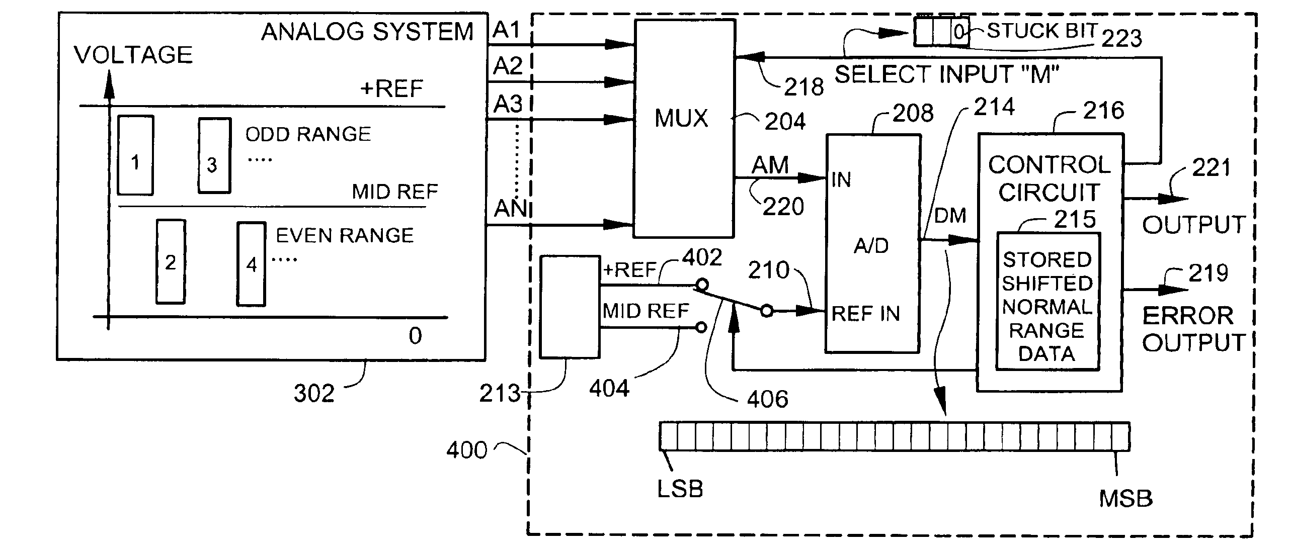
[0045]FIG. 4A illustrates a circuit 400 with a dynamically changing input range and an error output 219. Reference numbers used in FIG. 4A that are the same as reference numbers used in FIG. 3A identify the same or similar features.
[0046]Circuit 400 in FIG. 4A comprises a first switch 406 that couples to a reference input 210 on the A / D 208. A reference source 213 generates a first reference 402 and also generates a second reference 404 that is different than the first reference 402.
[0047]A control circuit 216 controls the first switch 406 to couple the first reference 402 to the analog-to-digital converter 208 when an odd-numbered analog input (A1, A3, . . . ) is selected. The control circuit 216 controls the first switch 406 to couple the second reference 404 to the analog-to-digital converter when an even-numbered analog input (A2, A4, . . . ) is selected. The switching provided by the first switch 406 shifts the range of the output of the A / D converter 208. In simple terms, the ...
PUM
 Abstract
Description
Claims
Application Information