Ground resistance monitor

Inactive Publication Date: 2002-05-28
RANCOM SYSTNS
View PDF3 Cites 53 Cited by
  • Summary
  • Abstract
  • Description
  • Claims
  • Application Information

AI Technical Summary

Benefits of technology

Using a synchronous rectifier in the ground measuring device of the present invention reduces the complexity of the remote sensor by removing the need for precision magnetic cores, complex distributed coil winding, and extensive magnetic shielding to prevent interaction between the drive and sense transformers. Placing a calibration table in nonvolatile memory in each

Problems solved by technology

The main drawback to this approach is that the earth ground--safety ground link must be opened.
This violates electrical code and OSHA rules unless all the equipment attached to the safety ground is turned off.
Shutting down equipment to compl

Method used


Image

  • Ground resistance monitor
  • Ground resistance monitor
  • Ground resistance monitor

Examples


Embodiment Construction

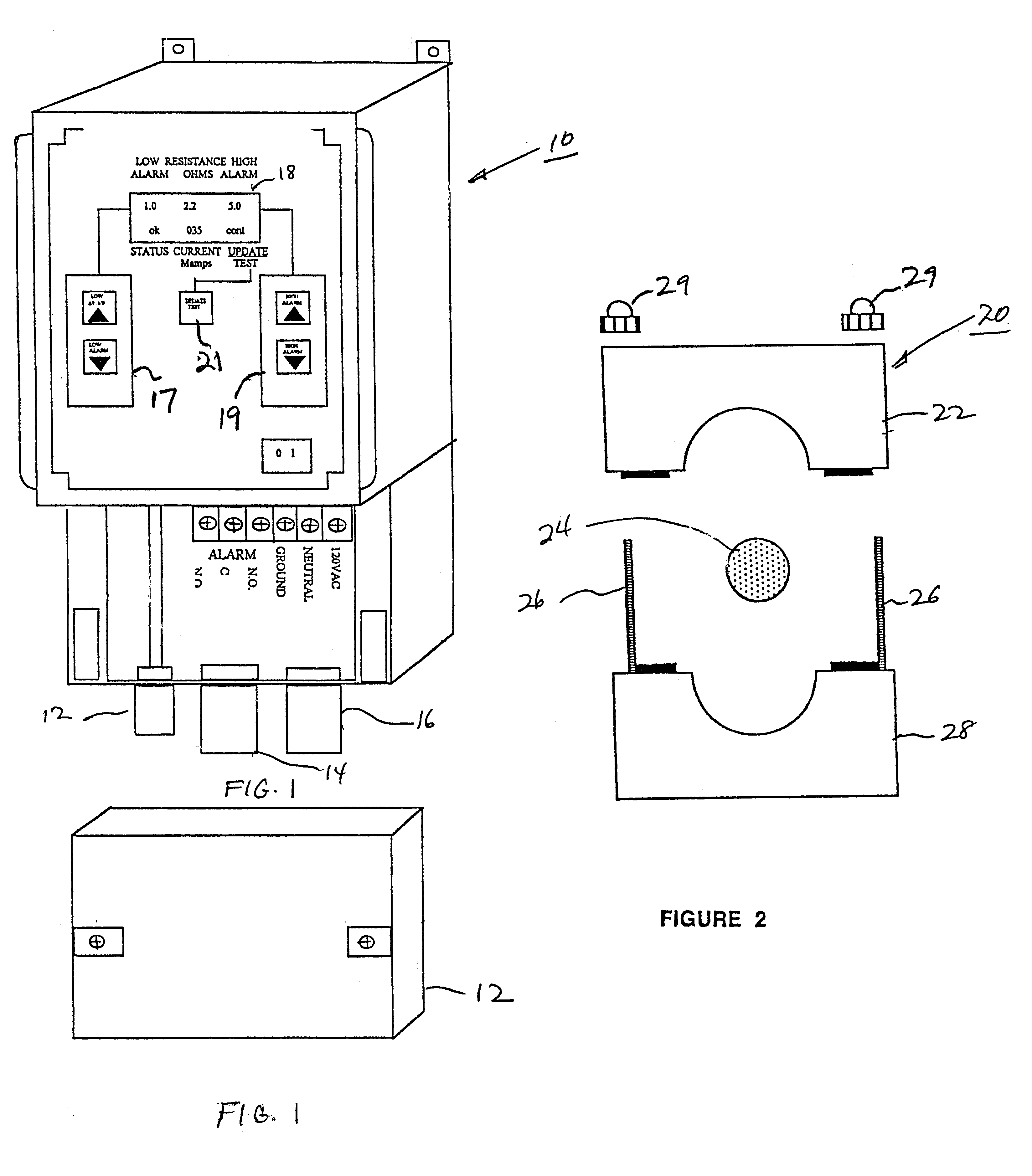
FIG. 1 is a perspective view of the novel ground resistance sensing device 10 of the present invention with the wiring component cover 12 removed. Leads 12, 14 and 16 are for the sensor connector, alarm and power functions, respectively. A display 18 provides the resistance readout in ohms (and milliamps) and also shows the preset low alarm value and high alarm value (described in more detail hereinafter) system status and mode condition. Panel switch 17 controls the low alarm value setting and panel switch 19 controls the high alarm value setting. Switch 21 enables the user to cycle through different modes as desired, i.e. continuous update; one per hour update, one per 8 hour update, and test.

FIG. 2 is an end view of remote sensor 20, showing top core portion 22, ground wire 24, mounting bolts 26 and sensor base 28.

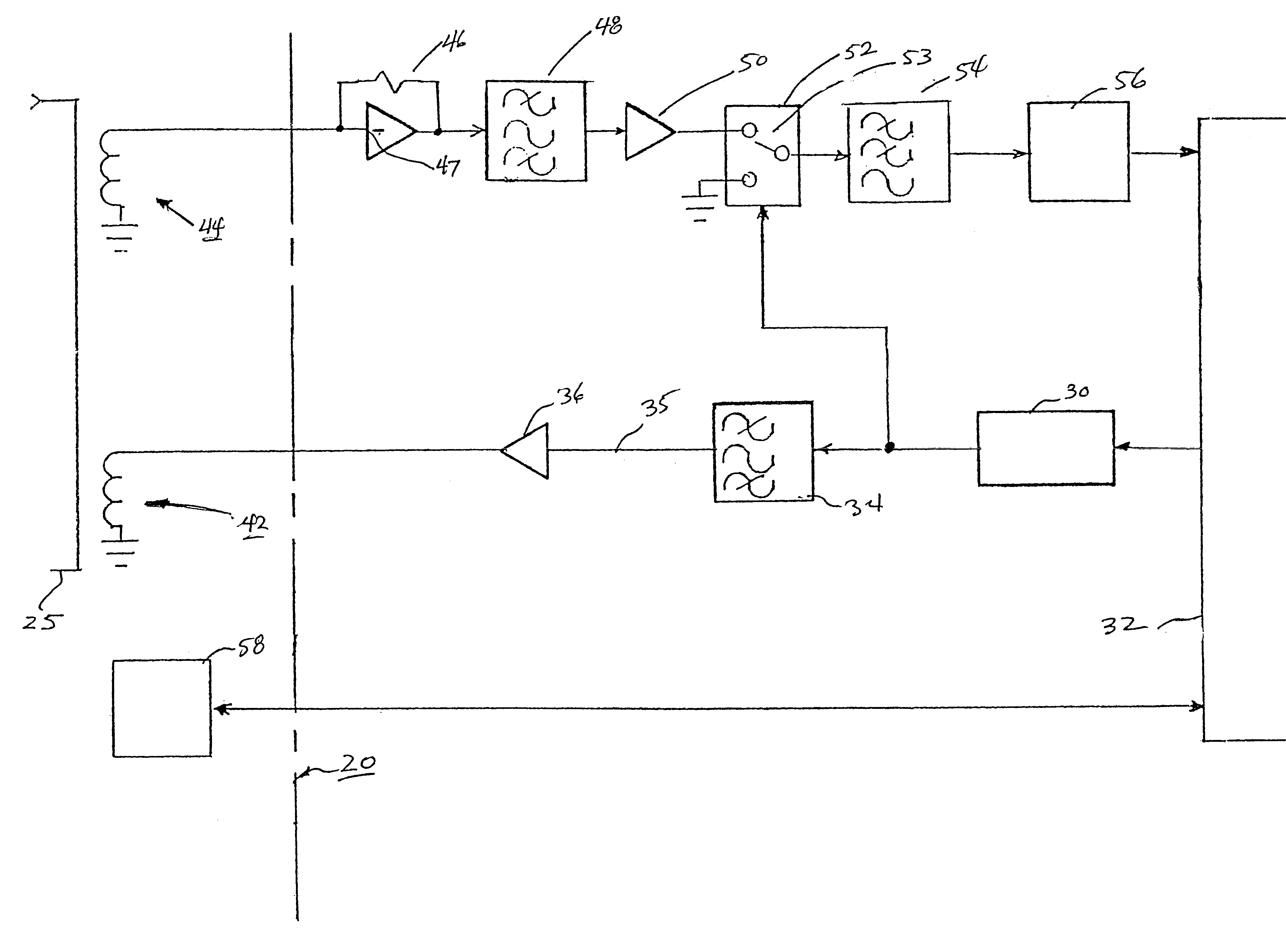
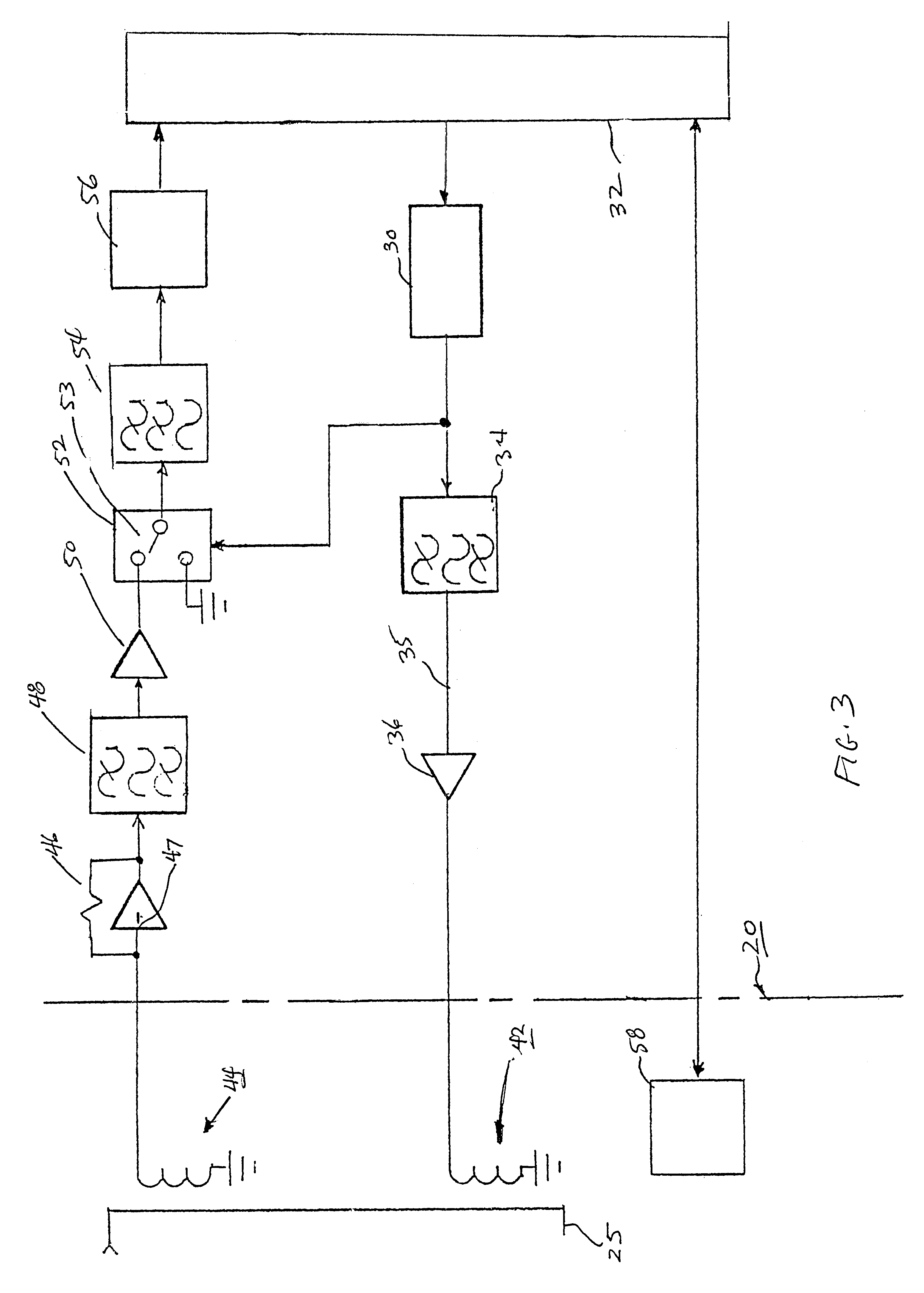
Referring now to the block diagram of FIG. 3, counter 30 generates a 1953 Hz square wave in response to the 8 Mhz crystal in microprocessor 32. The square wave is passe...


PUM


Abstract

A permanently mounted AC powered control/display unit and a remote sensor for use in measuring ground resistance. The sensor is permanently mounted around the earth grounding cable. The control display unit generates a 1953 Hz, 5 Vac sine wave which is sent via a cable to a 100:1 ratio drive transformer in the remote sensor. The transformer induces a 0.05 Vac sine wave in the ground cable. The resulting current is detected by a 100:1 turns ratio sense transformer. The current is returned via the cable to the control display unit and converted to a voltage, filtered, amplified and rectified by a synchronous rectifier. The rectified voltage is again filtered and presented to an analog to digital converter. A microprocessor reads the output of the analog to digital converter and the ground resistance is computed by using Ohm's Law (R=E/I), the result being shown on a display.

Description

1. Field of the InventionThe present invention provides an improved device for continuously measuring the electrical resistance between a grounding rod and earth ground; an alarm is triggered if the resistance is outside a preset range.2. Prior ArtSeveral prior art systems are currently available that measure electrical resistance between a grounding rod and earth ground.One such system requires the opening of the connection between the electrical safety ground and the earth grounding system. Current is injected into the earth grounding rod and a series of voltage measurements recorded. Ground resistance is calculated from these measurements. The main drawback to this approach is that the earth ground--safety ground link must be opened. This violates electrical code and OSHA rules unless all the equipment attached to the safety ground is turned off. Shutting down equipment to comply, such as telephone switch systems, air traffic systems and on-line computer centers is difficult to a...

Claims


Application Information

Patent Timeline
IPC IPC(8): G01R31/02G01R27/20
CPCG01R31/025G01R27/205G01R31/52
Inventor TISDALE, RALPH C.HIRSCH, EMANUEL H.
Owner RANCOM SYSTNS
Why Eureka
Try Eureka