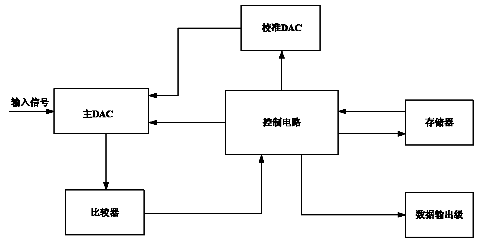
Sequential approximation analog to digital converter with digital correction and processing method thereof
An analog-to-digital converter, successive approximation technology, applied in analog/digital conversion, analog/digital conversion calibration/test, code conversion, etc. The effect of reducing errors
- Summary
- Abstract
- Description
- Claims
- Application Information
AI Technical Summary
Problems solved by technology
Method used
Image
Examples
Embodiment 1
[0033] Embodiment 1: It is assumed that the main DAC is composed of two stages, the upper 5-bit CDAC formed by the capacitor array and the lower 4-bit CDAC formed by the capacitor array.
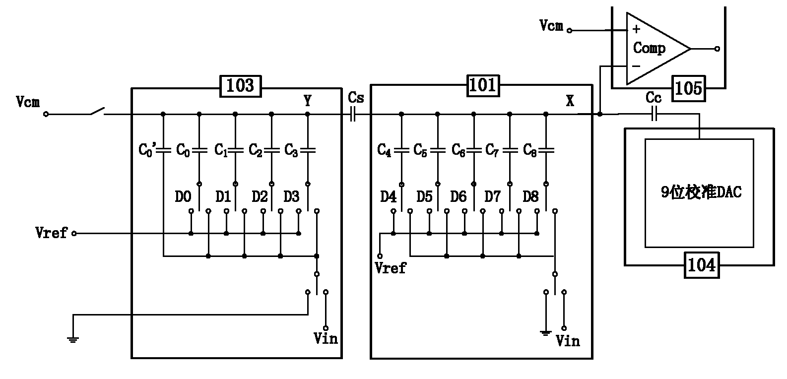
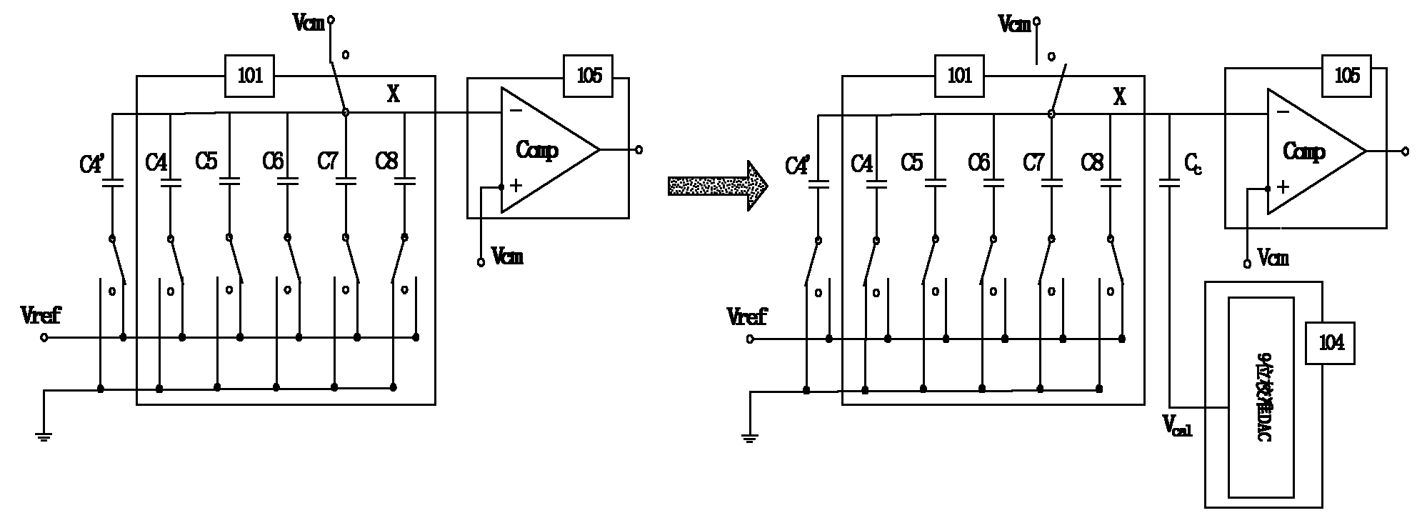
[0034] figure 2 Schematic diagram of the structure of the calibration DAC and the comparator for the main DAC implemented in two stages, including the upper 5-bit CDAC 101, the lower 4-bit CDAC 103, and the 9-bit calibration DAC 104 and comparator 105 in the main DAC. The high-order CDAC 101 and the low-order CDAC 103 are coupled through a unit capacitor Cs, and the output of the calibration DAC 104 is coupled with the output of the main DAC through a capacitor Cc.
[0035] Assume that the individual capacitors of the high-order CDAC 101 are:
[0036] C 8 =(2 4 +ΔC 8 ) C, C 7 =(2 3 +ΔC 7 ) C, C 6 =(2 2 +ΔC 6 ) C, C 5 =(2+ΔC 5 ) C, C 4 =(1+ΔC 4 )C, where ΔC i is the error of each capacitor, and C is the unit capacitance.
[0037] Assume that the respective capacitances of the...
Embodiment 2
[0083] Embodiment 2: In order to improve the precision of the analog-to-digital converter and ensure a certain monotonicity, the main DAC may also include an intermediate M-bit RDAC composed of a resistor string, and its structural diagram is as follows Image 6 As shown, it includes the high 5-bit CDAC 101 in the main DAC, the middle 3-bit RDAC 102 , the low 4-bit CDAC 103 , and the 9-bit calibration DAC 104 and comparator 105 .
[0084] In RDAC 102, V Ri It is the voltage of a resistor in the resistor string (determined by 3-8Decoder A, the input signal of 3-8DecoderA is D4, D5, D6) close to the ground potential, V Ri+1 It is a resistor in the resistor string (determined by 3-8Decoder B, the input signal of 3-8Decoder B is D4, D5, D6) close to V ref voltage at one end. Therefore, V Ri and V Ri+1 They are:
[0085] V Ri = V ref ( D 6 ...
PUM
| Property | Measurement | Unit |
|---|---|---|
| Coupling capacitance | aaaaa | aaaaa |
Abstract
Description
Claims
Application Information
 - R&D
- Intellectual Property
- Life Sciences
- Materials
- Tech Scout
- Unparalleled Data Quality
- Higher Quality Content
- 60% Fewer Hallucinations
Browse by: Latest US Patents, China's latest patents, Technical Efficacy Thesaurus, Application Domain, Technology Topic, Popular Technical Reports.
© 2025 PatSnap. All rights reserved.Legal|Privacy policy|Modern Slavery Act Transparency Statement|Sitemap|About US| Contact US: help@patsnap.com


