

Pll circuit
- Summary
- Abstract
- Description
- Claims
- Application Information
AI Technical Summary
Benefits of technology
Problems solved by technology
Method used
Image

Examples
embodiment
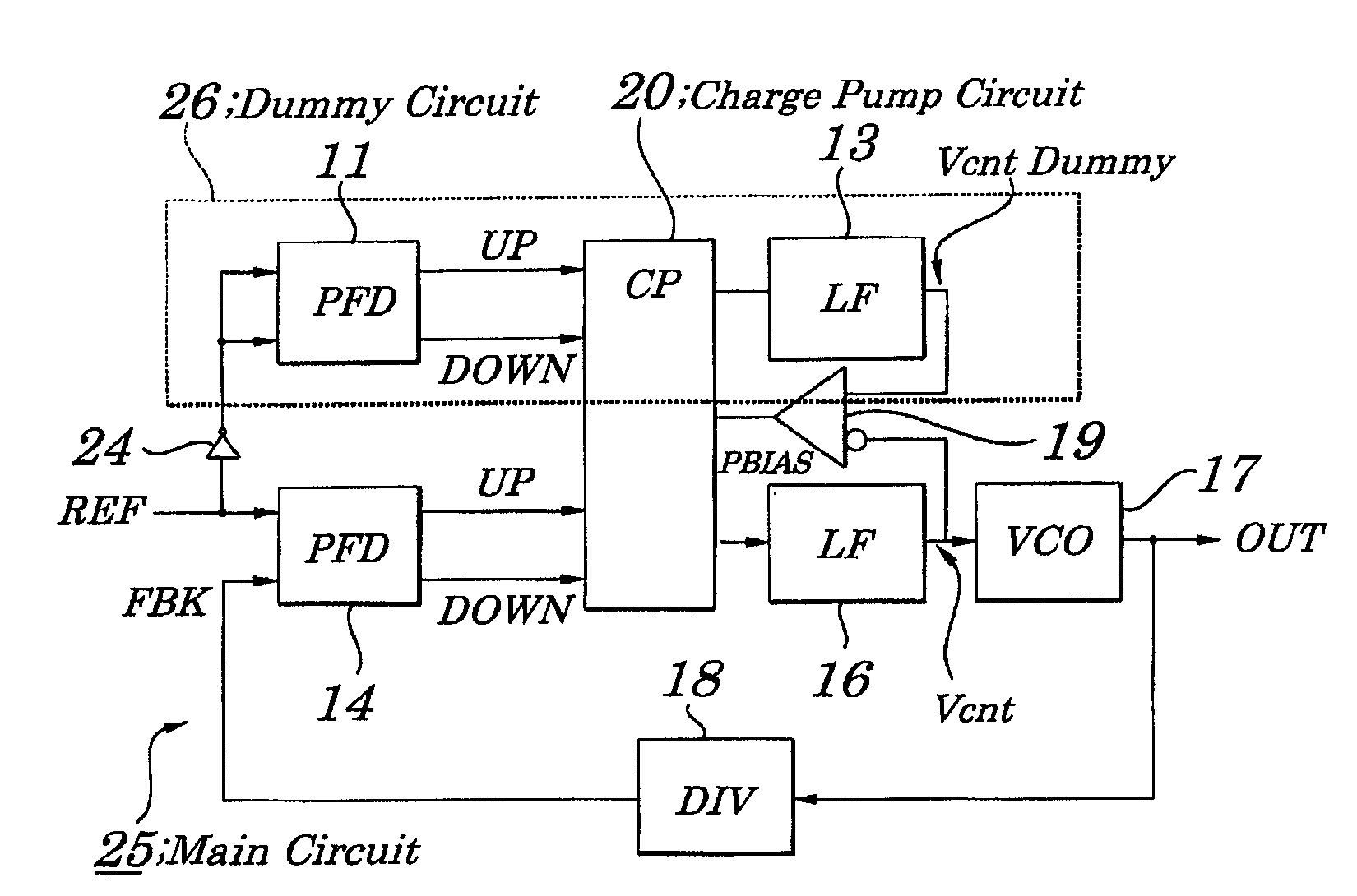
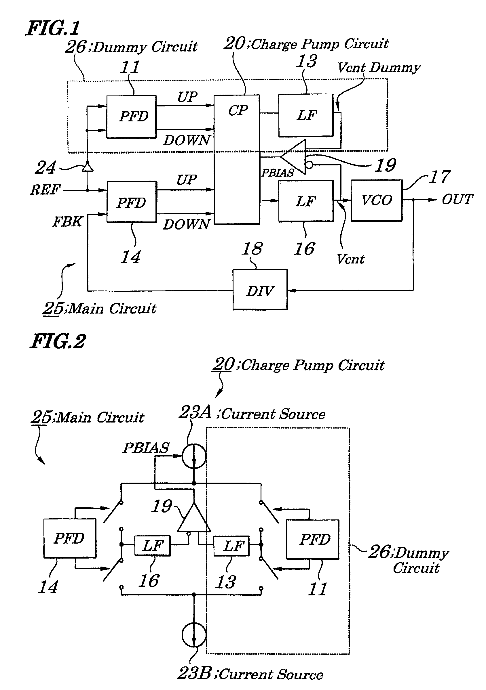
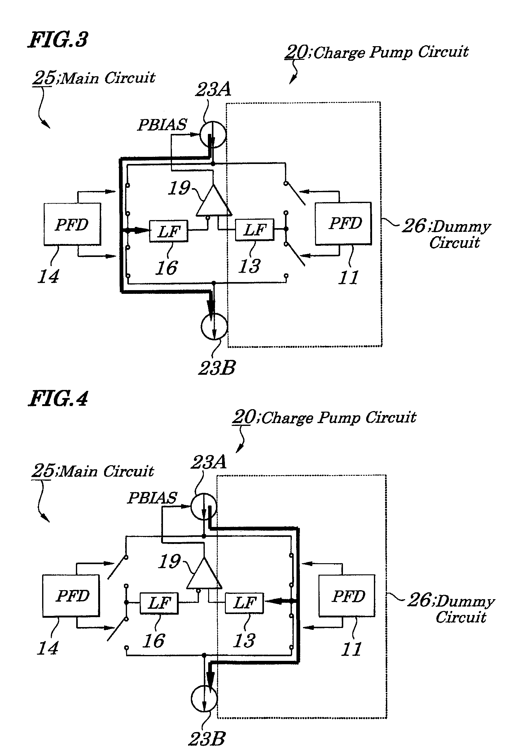
[0040]FIG. 1 is a block diagram showing configurations of a PLL circuit of an embodiment of the present invention. FIG. 2 is a diagram showing a state in which current sources are shared by a main circuit and a dummy circuit in the PLL circuit of the embodiment. FIG. 3 is a diagram explaining connection of current sources when the main circuit is operating in the PLL circuit according to the embodiment. FIG. 4 is a diagram explaining connection of current sources when the dummy circuit is operating in the PLL circuit according to the embodiment. FIG. 5 is a diagram showing an example of an operating time chart in the PLL circuit according to the embodiment. FIG. 6 is a diagram showing another example of an operating time chart in the PLL circuit according to the embodiment.
[0041]The PLL circuit of the embodiment, as shown in FIG. 1, includes a PFD 11, an LF 13, a PFD 14, an LF 16, a VCO (Voltage Controlled Oscillator) 17, a DIV (Divider) 18, an OPAMP (Operational Amplifier) 19, a ch...
PUM
 Abstract
Description
Claims
Application Information