Information transmitting system for use in factory

a technology of information transmission system and factory, applied in the field of information transmission system, can solve the problems of increased communication line, difficult to adapt, waste of memory

Inactive Publication Date: 2003-02-04
FANUC LTD
View PDF22 Cites 37 Cited by
  • Summary
  • Abstract
  • Description
  • Claims
  • Application Information

AI Technical Summary

Benefits of technology

It is an object of the present invention to provide an information transmitting system in a factory system which may transmit information simply among controllers without the complicated lead-around of a communication line or the need for a complicated communication protocol.
Because the plurality of controllers are interconnected via an Ethernet or a ring-type communication line in a daisy chain format, a parallel line connection format is made unnecessary, an I / O port or a communication line is prevented from increasing in number, and the lead-around of the communication line is prevented from being made complicated. This results in a reduction of the total cost required for setting up the devices. Further, since the storage means for the transmission of information is shared among all the controllers, the information can be shared simply without using a complicated communication protocol by incorporating the same kind of driver software corresponding to the storage means, such as a hard disc, into each controller.
Since the delivery of stocks is performed with the handling robot arranged on one of the ends of the plurality of parallel conveyors, the handling robot does not need to move in a travel direction of the conveyor, that is, in a longitudinal direction of the stock space, resulting in a reduction of time required for the delivery of stocks. Further, since the handling robot is disposed for the lower and upper stock spaces formed by the plurality of horizontally parallel conveyors so that the operational range of the handling robot reaches one of the ends of all the conveyors, it is sufficient to use only one handling robot, and besides, the stocks may be transshipped by one handling robot to or from another conveyance means, i.e., an automatic guided vehicle, without needing additional robots for warehousing and delivery, resulting in a reduction of cost required for constructing the system.
Further, each upper conveyor comprises a drive conveyor for feeding the pallets toward the handling robot, and each lower conveyor comprises an inclined coasting conveyor descending with the distance from the handling robot, so that the cost required for constructing the system is further reduced. The drive conveyor is adopted as the upper conveyor to ensure accurate operation so as to prevent the stocks from falling or dropping, and the inclined coasting conveyor is adopted as the lower conveyor to secure the stocks against falling or dropping as the lower conveyors are arranged at a low position.
Further, a lock pin to lock up the pallets or release the pallets from the locked state is arranged independently on.one of the ends of all the lower and upper conveyors on the side close to the handling robot, and as a result, the stocks already stored on the side of the stock space may be prevented by the lock pin from falling or dropping in delivery.

Problems solved by technology

Consequently, there arises a problem that with an increase of the controller in number, not only is an I / O port required for each controller but also a communication line increases in number (n number of controllers need n.multidot.
Further, a program to meet a plurality of communication protocols should be stored on each controller, resulting in a waste of memory.
Further, since a mode of communication is restricted by a structure of hardware such as an I / O port and the communication line, it is difficult to be adapted to system extension such as connection to additional controllers, and besides, it becomes hard to expand a communication facility by updating software.
Further, since means for making sure of required communications is dependent entirely on the hardware, there arises a problem in that equipment for the hardware is quite expensive, while the complicated hardware makes it difficult to perform maintenance and inspection.
Consequently, there is no guarantee that the pallets loaded with the products or the empty pallets are stored close to each other in the adjacent cells.
Accordingly, in the case of not only taking out the empty pallets, but also storing the pallets loaded with products, the stacker crane robot needs to move vertically and horizontally along the solid pallet stocker, resulting in a waste of access time.
Although it is possible to arrange the cells stored with the pallets loaded with products and the cells stored with the empty pallets into blocks by minutely controlling the addresses of the stock placing cells, there arises a problem that the stacker crane robot still wastes access time since the stacker crane robot has to move vertically and horizontally astride the blocks when alternating between storing the pallets loaded with products and taking out the empty pallets.
Further, in the case where it is necessary to sort the storage locations of the pallets loaded with products according to the product type, the number of the blocks increases, and there arises a problem that a more complicated operation is required.
It is possible to cope with the above problem by arranging the solid pallet stockers to correspond to the kinds of products (in this case, each of the solid pallet stockers corresponds to the block), but as a matter of course, each solid pallet stocker needs to be equipped with the stacker crane robot, resulting in an increase of cost required for constructing the system.
Besides, even doing so, the stacker crane robot still needs to move vertically and horizontally, and the access time itself is not reduced very much.
Further, since the stacker crane robot is just operated to transfer the stocks to or from the solid pallet stocker constituting stock spaces and cannot transship the stocks to or from another conveyance means, e.g., an automatic guided vehicle, there arises a problem that equipment constituting an automated system needs to be installed at quite an expense because additional robots for warehousing and delivery are required to transship the stocks, causing the equipment to be large scale.

Method used


Image

  • Information transmitting system for use in factory
  • Information transmitting system for use in factory
  • Information transmitting system for use in factory

Examples


Embodiment Construction

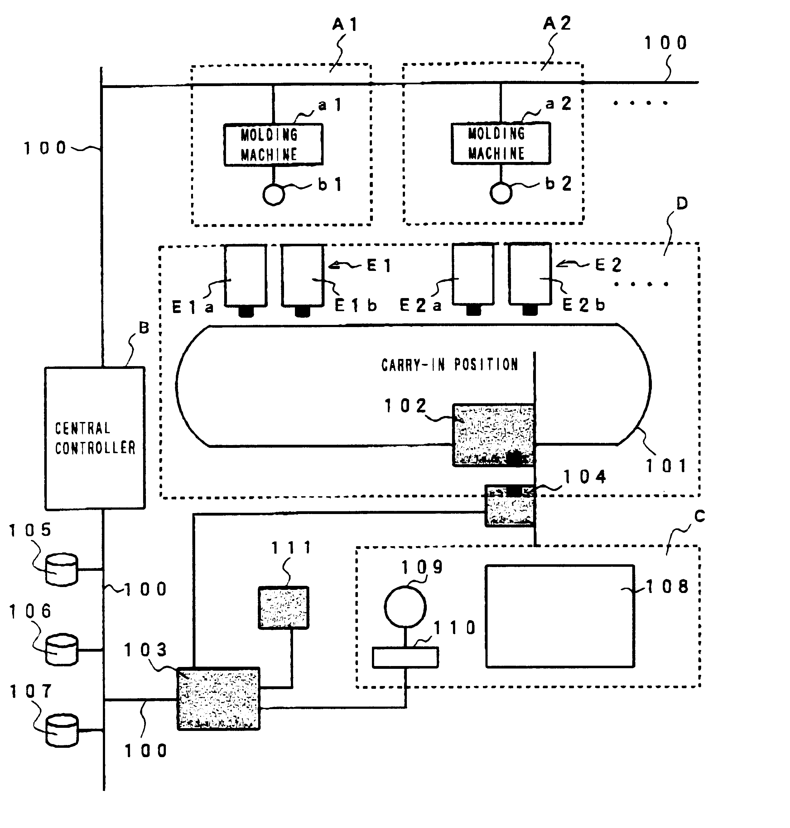
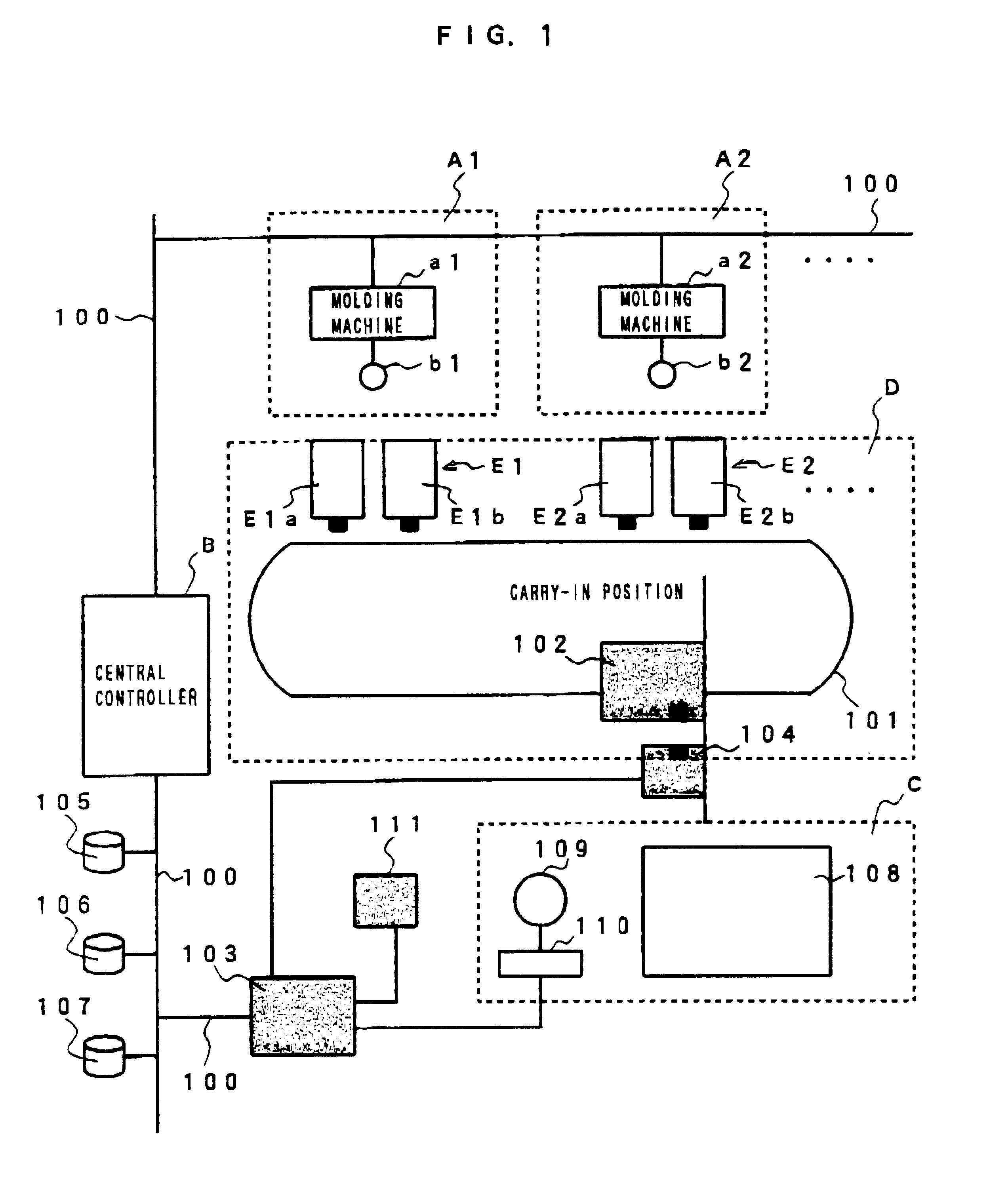
FIG. 1 schematically shows an arrangement of a factory employing an information transmitting system of the present invention, and in this embodiment, there is shown a stock cell to collect and store molded products produced by injection molding machines.

As shown in FIG. 1, this factory system comprises a plurality of molding cells Ai (where i=1,2, . . . max) and max is the maximum number of molding cells, arranged in an injection molding factory, a central controller B to control these molding cells, a stock cell C forming a robot warehouse, and a conveyance cell D to transfer molded products and pallets between the plurality of molding cells Ai in the injection molding factory and the stock cell C.

Among these components, each molding cell Ai comprises an injection molding machine ai(where i=1,2, . . . max), a controller for the injection molding machine (not shown), a handling robot bi (where 1,2, . . . max) serving as a pallet exchanging device for the injection molding machine ai...


PUM

PropertyMeasurementUnit
distanceaaaaaaaaaa
transmissionaaaaaaaaaa
access timeaaaaaaaaaa

Abstract

An information transmitting system for use in a factory, which is capable of transmitting information among controllers simply without the complicated lead-around of a communication line nor the need of complicated communication protocol. A controller for every molding cell Ai, where i=1,2 . . . max and max is a maximum number of molding cells, a conveyance controller to control an automatic conveyor, a stock cell and a centralized controller are connected to each other via an Ethernet line to provide a common information storage unit, and information is transmitted among the controllers through the common information storage unit. Since there is no need of parallel communication lines between the controllers, an I / O port or a communication line may be prevented from increasing in number and the lead-around of the communication line is prevented from being complicated, resulting in a reduction of cost required for setting up the devices.

Description

This Application is a 371 of PCT / JP97 / 04424 filed Dec. 3, 1997.The present invention relates to an information transmitting system for transmitting information among controllers of various machines for use in a factory.For the purpose of interconnecting controllers of various machines for use in a factory so as to enable the transmission of information among the controllers, it is necessary to connect each controller to all the other controllers in parallel. Consequently, there arises a problem that with an increase of the controller in number, not only is an I / O port required for each controller but also a communication line increases in number (n number of controllers need n.multidot.(n-1) / 2 number of communication lines).With an increase of the number of communication lines, a thicker cable is needed, and an independent communication protocol is required for every combination of controllers for communication between the specific controllers. Further, a program to meet a plurality...

Claims


Application Information

Patent Timeline
Patent Type & Authority Patents(United States)
IPC IPC(8): G05B19/418B65G1/137B23Q41/00B65G61/00G05B15/02G05D1/02G06Q50/00G06Q50/04
CPCG05B19/4185G05B2219/31089G05B2219/31094G05B2219/31145Y10T29/53004G05B2219/34192Y10T29/53174Y10T29/53048Y10T29/53009G05B2219/31324Y02P90/60Y02P90/02
Inventor KAMIGUCHI, MASAOSAITO, OSAMUKUKITA, ATSUYUKI
Owner FANUC LTD
Why Eureka
Try Eureka