Wall hanger, mounting kit, and method

a technology for mounting kits and hangers, which is applied in the direction of nail dispensers, manufacturing tools, machine supports, etc., can solve the problems of tearing the drywall covering, affecting the positioning of the hanger, and affecting the appearance of the hanger,

Inactive Publication Date: 2000-03-28
DONOVAN CHARLES A
View PDF23 Cites 38 Cited by
  • Summary
  • Abstract
  • Description
  • Claims
  • Application Information

AI Technical Summary

Benefits of technology

It is a further object to provide a hanger that utilizes affixing members of sufficiently small diameter to avoid making large holes in a wall.
It is a further object to provide a method for hanging an object on a vertical surface such as a wall that minimizes the damage done to the vertical surface.
It is an additional object to provide a method for affixing a hanger to a vertical surface that also minimizes the damage done to the wall.
The use of pleating pins has been found to be advantageous because a minimum amount of damage is done to a wall with their insertion and removal. It has been found that most types of walls, including but not limited to drywall, plaster, wood, and plaster, and all types of wall coverings, including but not limited to wallpaper and vinyl, are amenable to having the wall hanger of the present invention mounted thereto.
The hanger additionally has support means protruding from its second side. The support means is positioned a first distance from the top edge and a second distance greater than the first distance from the bottom. Such a positioning serves in use to translate a portion of the gravitational force exerted by a hung object into a force directed into the wall, which relieves the stress placed upon the pins.
A pilot tool is also provided as an additional aspect of the present invention. This tool, which is capable of starting holes in a semipermeable wall surface preparatory to inserting the pin through the hanger, has a pointed borer at one end and a handle at the other end. The borer is dimensioned for making holes in a wall after having passed through a bore of the wall hanger. The borer has a length dimensioned to start a hole in a wall sufficiently deep to permit an easy insertion of a pleating pin thereinto. The bore's handle has a first end, at which it is affixed to the borer, and a second end, which has an indentation therein dimensioned to surround the head of a pin for pushing the pin through a bore in the hanger, into a started hole, and further into the wall until the head is substantially flush with the hanger's second side.

Problems solved by technology

Thus most of these devices, when used on a semipermeable material such as drywall, will leave unsightly holes when removed and may even tear the drywall covering.
Such holes also render it impossible to make minor adjustments to the position of the hanger, such as are frequently desired when attempting to level an object or to align one object with another.
In addition, in the process of making the hole, wall material is lost, weakening the area of the wall where an object is to be hung.
This problem is so severe in rental units and dormitories, for example, that walls must routinely be replaced every 7-10 years.
Locating an area to hang the object can also present a problem.
Typically such hangers cannot support much weight, and, if they fail, tear the wall surface or wallpaper to which they are applied.
The positioning of the elements of prior hangers has also not been optimal.
When weight is applied to the device, a downward force is experienced, tending to pull the hanger downward, which in turn causes the nail, screw, or bolt to bend and / or to tear the wall.
A horizontal distance between the point at which force is applied and the wall further introduces a torque, tending to pull the top of the hanger away from the wall, which can cause failure in the form of pulling the support out of (or away from in the case of an adhesive backing) the wall.
Any of these failures can also, of course, damage the hanging object.
This has made it difficult to position an object precisely, as adjustments must be made for the location of the hanging element.
Further, an imminent failure cannot be spotted, since the nail, bolt, or screw is hidden from view.
The methods and tools utilized to affix known hanging devices to a wall have not been satisfactory.
For example, the tools used to drive the anchoring means of the devices, such as hammers, can also cause damage to the wall (or to the user).

Method used


Image

  • Wall hanger, mounting kit, and method
  • Wall hanger, mounting kit, and method
  • Wall hanger, mounting kit, and method

Examples


embodiment 10

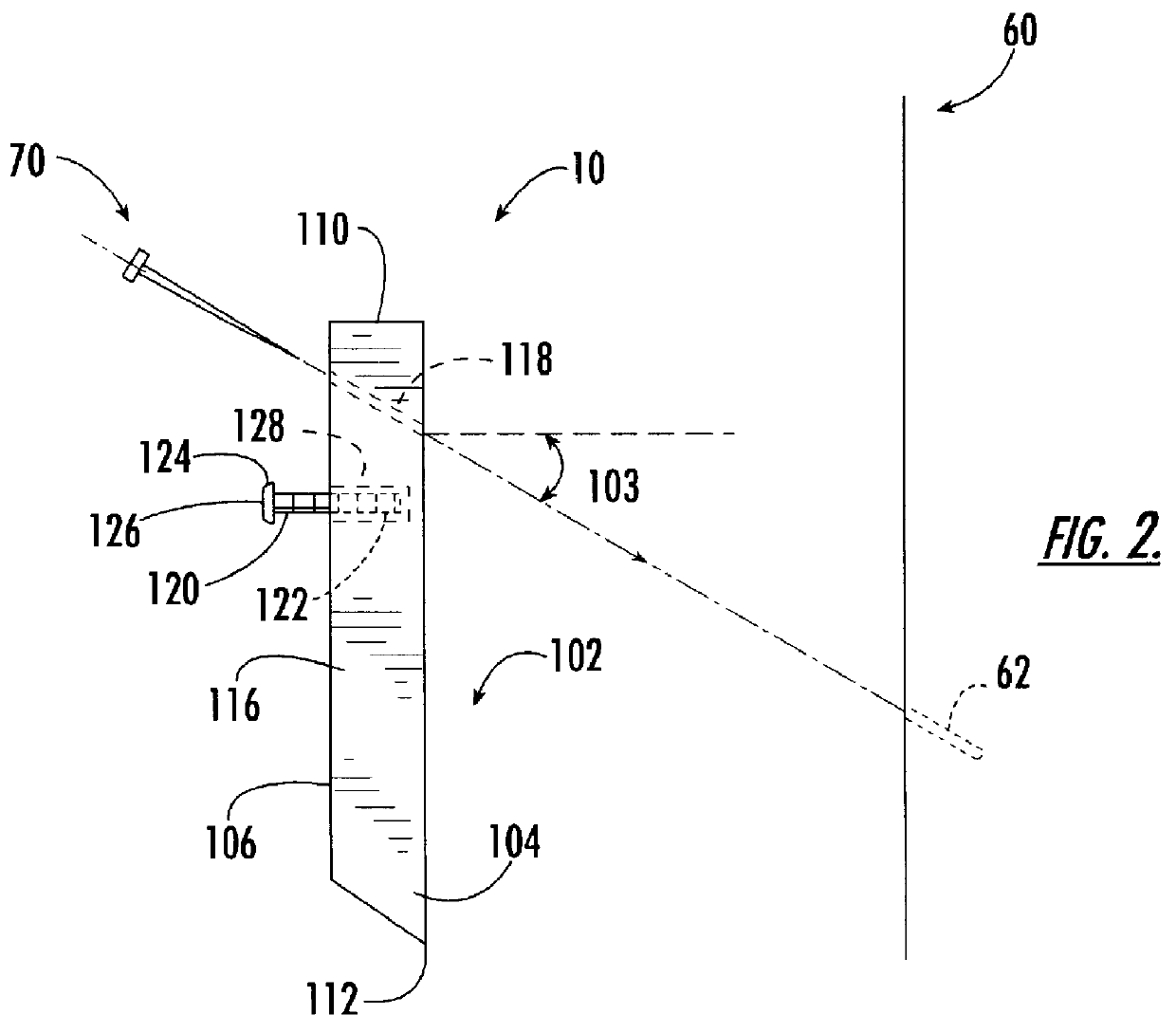
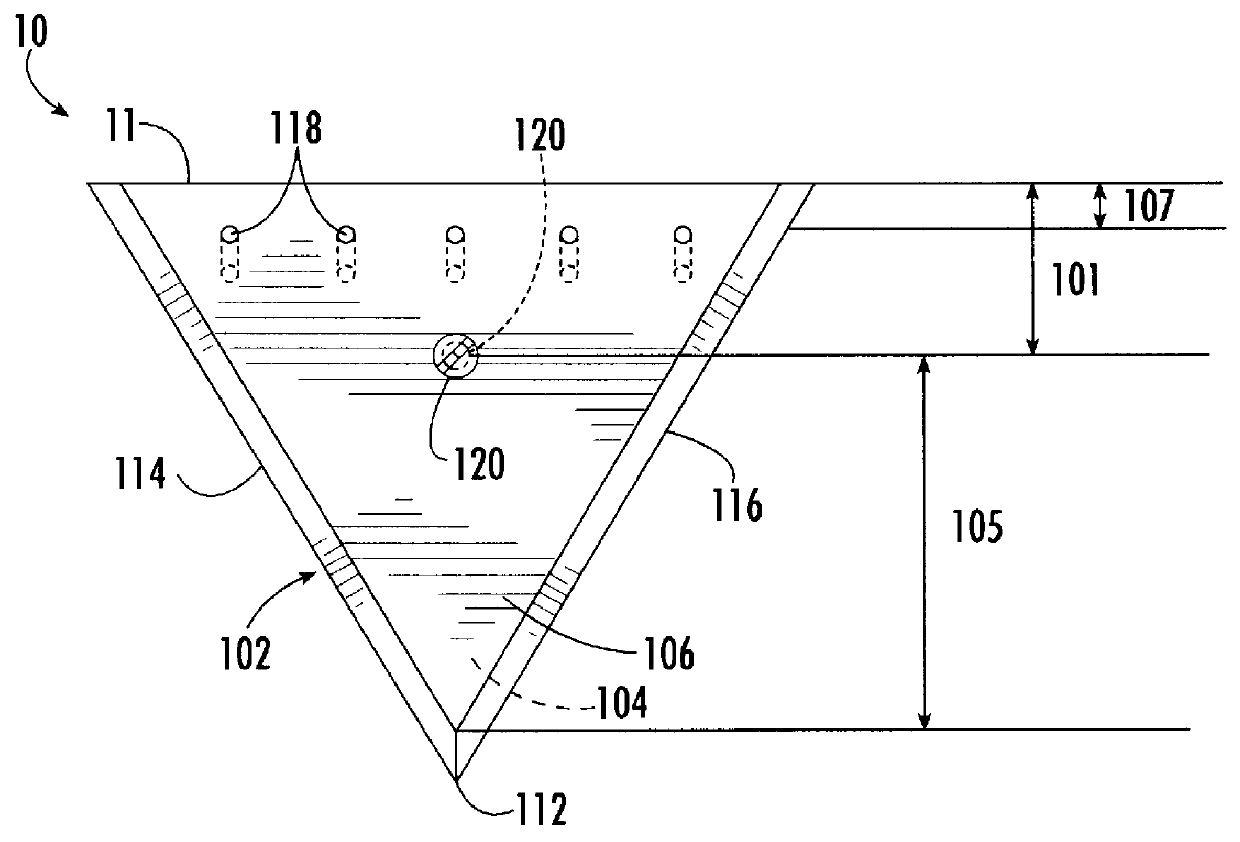
The wall hanger 10 of this embodiment has a generally equilateral triangular shape, although this is not intended as a limitation, as other shapes could be readily conceived by one of skill in the art. The hanger 10 is preferably made of a stiff, clear material, such as a plastic like acrylic or Lexan. The hanger 10 has a generally planar first side 104 for interfacing with a wall 60 and a generally planar second side 106 opposed to first side 104. Since this embodiment 10 is clear, determining the location for hanging is facilitated. Hanger 10 further has a top edge 110 along a first edge of the triangular shape and a bottom 112 defined by the point formed by the junction of the beveled second 114 and third 116 edges of the triangular shape. The edges' 114,116 bevels extend outward from the second side 106 to the first side 104.

Along the top edge 110 are disposed a plurality of narrow bores 118. Bores 118, in a preferred embodiment numbering five, extend in a direction away from to...

first embodiment

a support means of the picture hanger (FIGS. 1 and 2) comprises a screw 120 having a first end 122 press-fit into base 102 and a second end 124 having a screw head 126 for restraining a picture wire or the frame of a picture when the wire or frame has been hung upon screw 120.

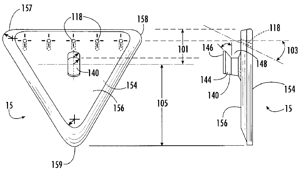
An alternate embodiment of the triangular picture hanger is shown in FIGS. 3 and 4, indicated by the reference numeral 15. A difference between this embodiment and that discussed above 10 is that the support means comprises a molded hook 140 having a first end 142 integrally connected to second side 156 and a second end 144 having an upwardly extending portion 146 defining a valley 148 onto which a picture wire or the like may be hung and restrained by the upwardly extending portion 146.

An additional difference is that the corners 157-159 are rounded, providing a pleasing appearance and decreasing a chance of scraping the wall surface with a sharper corner.

In either hanger 10 or 15, it is preferable that the ob...


PUM


Abstract

The wall hanger of the present invention is designed to minimize the damage done to a wall when hung thereon. The wall hanger has a plurality of narrow bores angling generally downward through which pleating pins may be inserted to anchor the wall hanger. The wall hanger additionally has a support member from which may be hung an object. The bores and support member are configured to maximize a proportion of gravitational stress transferred to the wall to relieve stress on the pins. A pilot tool is also disclosed that starts a hole in the wall through the bores in the hanger and then is used to push a pin through the bore, into the pretapped hole in the wall, and further into the wall until its head is flush with the hanger. A kit is provided that consists of a wall hanger and a mounting tool. In addition, a method is provided for mounting a wall hanger to a wall.

Description

1. Field of the InventionThe present invention relates to devices for mounting objects to a wall or a similar vertical surface, and, more particularly, to devices for affixing objects to a semipermeable surface such as drywall.2. Description of Related ArtVarious implements have been devised to hang objects from walls. Most such hangers have utilized screws, bolts, or nails, which typically must have a sufficiently large diameter to support the weight of the object. Thus most of these devices, when used on a semipermeable material such as drywall, will leave unsightly holes when removed and may even tear the drywall covering. Such holes also render it impossible to make minor adjustments to the position of the hanger, such as are frequently desired when attempting to level an object or to align one object with another. In addition, in the process of making the hole, wall material is lost, weakening the area of the wall where an object is to be hung. This problem is so severe in rent...

Claims


Application Information

Patent Timeline
Patent Type & Authority Patents(United States)
IPC IPC(8): A47G1/16A47G1/20
CPCA47G1/205
Inventor DONOVAN, CHARLES A.
Owner DONOVAN CHARLES A
Why Eureka
Try Eureka