Multi-stage dispensing mat

a multi-stage, mat technology, applied in the direction of lighting and heating equipment, tobacco, heating types, etc., can solve the problems of unnecessarily high levels of insecticide or other active being dispensed into the air, unnecessarily increasing the cost of such heaters, and reducing the service life of such heaters, so as to achieve the desired protection very quickly, reduce the effect of bleeding and reducing the cost of heating equipmen

Inactive Publication Date: 2006-05-16
SC JOHNSON & SON INC
View PDF10 Cites 9 Cited by
  • Summary
  • Abstract
  • Description
  • Claims
  • Application Information

AI Technical Summary

Benefits of technology

[0022]In yet another form of the invention there is provided a method of constructing such a dispensing mat. One obtains a slab of a substrate material. One then compresses a portion of the slab with a hot forming die to form a moat wherein the moat defines a first slab portion and a second slab portion, preferably connected at the bottom of the moat. One then deposits a first volatile material in the first portion of the mat, and deposits a second volatile material in the second portion of the mat. The moat acts to minimize bleed between the two portions of the mat (e.g. while the mat is being stored for shipment, inventory, or store display).
[0023]When used as an insect control device, the device of the invention allows the user to achieve desired protection very quickly, without sacrificing long-term protection. When dispensing a deodorizer or fragrance, the invention has the advantage of covering over existing malodors very quickly (e.g. in a bathroom), without sacrificing the ability to provide fragrance over the long term.
[0024]The present invention is further capable of turning a disadvantage of inexpensive heaters (non-uniform heating across the heating face) into an advantage. This is achieved by centrally placing the fast release portion.
[0025]These advantages are achieved while permitting a very efficient manufacturing process to be able to produce the item. A low cost hot forming die stamping operation can quickly form the moat. When the hot forming die is pressed against the upper wall of the substrate for forming the moat, it melts the substrate leading to the close of the pores in the substrate and thus the formation of a barrier along the walls of the moat. The barrier can prevent or reduce bleeding between the volatile material in the first substrate portion and the volatile material in the second substrate portion. Therefore, a mat with chemically separated regions is made without involving the assembly of multiple parts and / or the use of a moat filler as a separator to prevent bleeding.

Problems solved by technology

This is a particular problem where the product is primarily designed to provide a prolonged release of active (e.g. to provide overnight protection against mosquitoes).
However, actives are often costly, and in any event the increased concentration may lead to unnecessarily high levels of insecticide or other active being dispensed into the air after the initial period.
In any event, including this capability in future heaters would unnecessarily increase the cost of such heaters.
However, this approach is not suitable for a mat where the entire bottom of the mat is designed to be exposed to the heat source at once.
Unfortunately, this approach requires the user to sequentially move the slab when the next stage of usage is desired.
These mats were somewhat difficult to manufacture because the material had to be cut entirely through, resulting in multiple pieces needing to be assembled.
This added to the cost of production.
This method also required difficult manufacturing steps.

Method used


Image

  • Multi-stage dispensing mat
  • Multi-stage dispensing mat
  • Multi-stage dispensing mat

Examples


Embodiment Construction

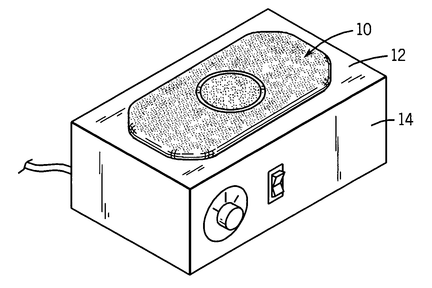
[0032]Referring first to FIG. 1, a mat 10 is shown placed upon a horizontal burner face 12 of an electric heater 14. The heater 14 can be an electrical-resistance heater, such as the heater sold by as the RAID® heater by S. C. Johnson & Son, Inc. However, other heaters could also be used, including without limitation those with horizontal, vertical, or other orientation of their heating surfaces.

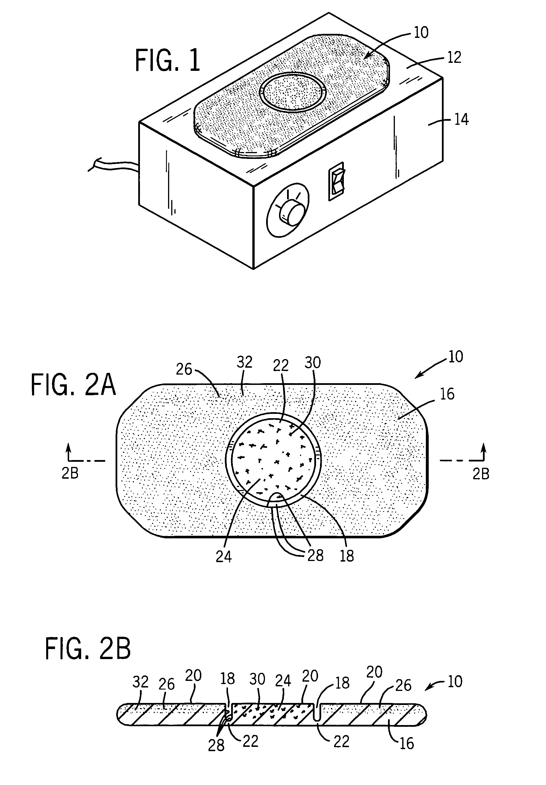
[0033]A first preferred embodiment of the mat is shown in other views in FIGS. 2A and 2B. Mat 10 includes a slab-like body 16 made of a porous material suitable for retaining volatile materials. Further, the porous slab material is sufficiently heat sensitive so as to melt when contacted by a hot forming die but also sufficiently heat resistant so as to not significantly melt in the presence of heat from heater 14. Slab-like body 16 has a circular moat 18 on upper surface 20 formed by pressing upper surface 20 with a hot forming die (see U.S. Pat. No. 3,075,862 for an example of using a hot ...


PUM

PropertyMeasurementUnit
temperatureaaaaaaaaaa
operating temperatureaaaaaaaaaa

Abstract

Disclosed herein are mats for dispensing volatile materials. A mat of the present invention includes a moat on an upper surface of the mat defining a first mat portion and a second mat portion, preferably connected at the bottom of the moat. Both portions are impregnated with the same or different volatiles. The moat is formed by pressing the upper wall of the mat with a hot forming die. While pressed against the upper wall, the hot die melts the mat material leading to the close of the pores in the material and as a result, a barrier along moat walls is formed. The moat and barrier act to prevent or reduce bleeding of the volatiles between two portions of the mat. The mat provides for both instant burst of volatile and then a sustained vaporization of volatile. Methods for making and using the mat are also disclosed.

Description

CROSS-REFERENCE TO RELATED APPLICATIONS[0001]Not applicable.STATEMENT REGARDING FEDERALLY SPONSORED RESEARCH / DEVELOPMENT[0002]Not applicable.BACKGROUND OF THE INVENTION[0003]The present invention relates to dispensing volatile materials such as insecticides, insect repellants, fragrances, and deodorizers. It provides mats designed to be placed on a heater to release the volatile material when the mat is heated.[0004]It is known to impregnate or coat a solid porous mat, including a plastic mat, with a volatile material, and / or to place a volatile material in a metal pan-like structure. These structures are then placed on heaters to cause the volatile to vaporize into the ambient air. See generally U.S. Pat. No. 6,031,967 and WO 99 / 66791. The disclosure of these publications, and of all other publications referred to herein, are incorporated by reference as if fully set forth herein.[0005]However, there can be a time lag between the initiation of the heating of the mat and when the co...

Claims


Application Information

Patent Timeline
Patent Type & Authority Patents(United States)
IPC IPC(8): A61M16/00A61L9/04A01M1/20A61L9/03
CPCA01M1/2077A61L9/015A01M1/20A61L9/03
Inventor FLASHINSKI, STANLEY J.
Owner SC JOHNSON & SON INC
Why Eureka
Try Eureka