Cardiac stimulating device

a technology of stimulating device and electrode, which is applied in the direction of heart stimulator, electrotherapy, therapy, etc., can solve the problems of difficulty in positioning electrode to pace and sense the left atrium

Inactive Publication Date: 2006-05-16
ST JUDE MEDICAL
View PDF6 Cites 98 Cited by
  • Summary
  • Abstract
  • Description
  • Claims
  • Application Information

AI Technical Summary

Problems solved by technology

It is well known in the art that it is difficult to...

Method used


Image

  • Cardiac stimulating device
  • Cardiac stimulating device
  • Cardiac stimulating device

Examples


Embodiment Construction

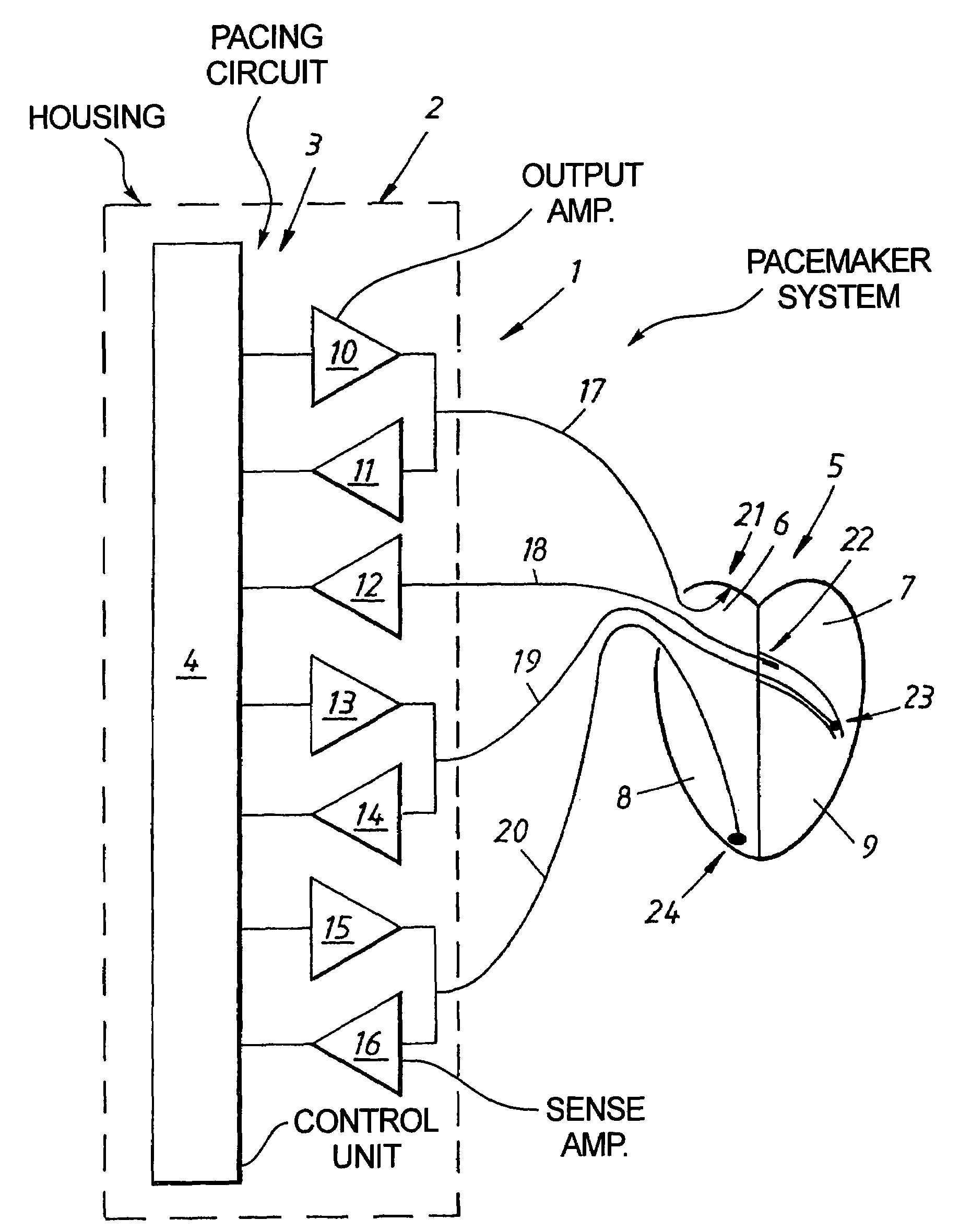
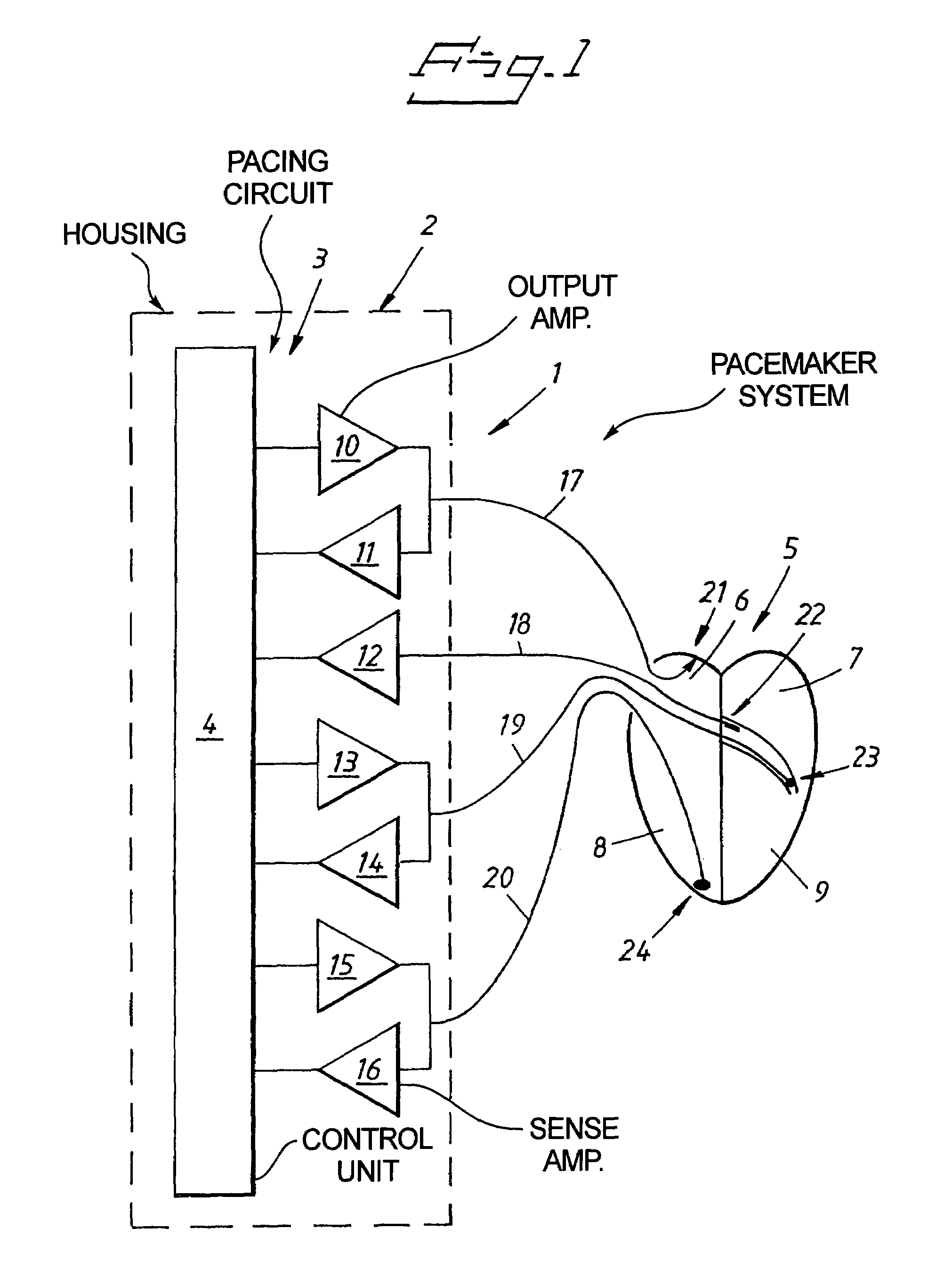
[0010]FIG. 1 shows an implantable cardiac stimulating device, hereinafter also called a pacemaker system 1, according to the invention. The pacemaker system 1 has a housing 2 and leads 17, 18, 19, 20. A pacing circuit 3 is enclosed in the housing 2. The pacing circuit 3 is adapted to be connected to lead 19 with electrode 23. FIG. 1 shows such an electrode 23 which is connected to the pacemaker via lead 19. The first electrode 23 is adapted to be positioned to stimulate the left ventricle 9 of the heart 5. The pacing circuit 13 is also adapted to be connected to a second electrode 22. FIG. 1 shows such a second electrode 22 connected to the pacing circuit 3 via a lead 18. The second electrode 22 is positioned to sense depolarizations of the left atrium of the heart 5. The pacing circuit 3 is further adapted to be connected to a third electrode 21. FIG. 1 shows such a third electrode 21 connected to the pacing circuit 13 via a lead 17. The third electrode 21 is positioned to sense de...


PUM


Abstract

An implantable cardiac stimulating device has a pacing circuit connected via an electrode lead system to a first electrode which stimulates and detects activity in the left ventricle, a second electrode to stimulate and detect activity in the right atrium, and to a third electrode to detect activity in the left atrium. Upon the occurrence of a paced or sensed depolarization of the right atrium, a first AV-delay is started. When the subsequent left atrial depolarization is detected, a new AV-interval is started that is optimized for the left side of the heart. Either the left ventricle only, or both ventricles, is paced at the optimized left side AV-interval.

Description

BACKGROUND OF THE INVENTION[0001]1. Field of the Invention[0002]The present invention relates to an implantable cardiac stimulating device of the type having the capability to sense and stimulate the right atrium, to sense the left atrium, and to sense and stimulate the right and left ventricles, respectively.[0003]2. Description of the Prior Art[0004]Most pacers are arranged to stimulate the right ventricle of the heart, but it is also known to stimulate the left ventricle. In particular for the treatment of congestive heart failure or other severe cardiac failures it is known to stimulate the left ventricle, or both ventricles, in order to optimize the hemodynamic performance of the heart.[0005]U.S. Pat. No. 5,720,768 describes different possible electrode positions in order to stimulate or sense the different chambers of the heart. It is also disclosed that the conduction time from right atrium to left atrium may be observed and the left atrium may be paced if the conduction time...

Claims


Application Information

Patent Timeline
IPC IPC(8): A61N1/362A61N1/368
CPCA61N1/3627A61N1/3682
Inventor HOIJER, CARLSCHULLER, HANS
Owner ST JUDE MEDICAL
Why Eureka
Try Eureka