Method and System for Adaptive Bi-Ventricular Fusion Pacing

Active Publication Date: 2017-08-03
PACESETTER INC
View PDF4 Cites 3 Cited by
  • Summary
  • Abstract
  • Description
  • Claims
  • Application Information

AI Technical Summary

Problems solved by technology

However, some patients fail to respond to conventional CRT.
Existing BiV pacing techniques do not adapt to change

Method used


Image

  • Method and System for Adaptive Bi-Ventricular Fusion Pacing
  • Method and System for Adaptive Bi-Ventricular Fusion Pacing
  • Method and System for Adaptive Bi-Ventricular Fusion Pacing

Examples


Embodiment Construction

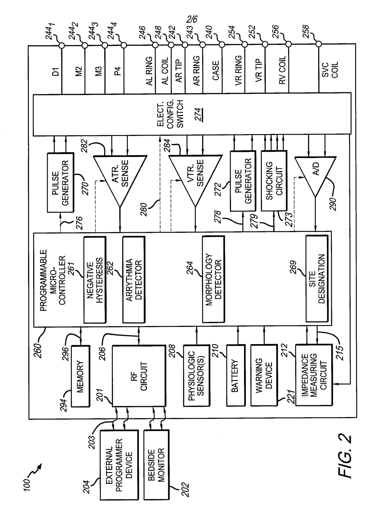
[0016]The systems described herein can include or represent hardware and associated instructions (e.g., software stored on a tangible and non-transitory computer readable storage medium, such as a computer hard drive, ROM, RAM, or the like) that perform the operations described herein. The hardware may include electronic circuits that include and / or are connected to one or more logic-based devices, such as microprocessors, processors, controllers, or the like (collectively “processors”). These devices may be off-the-shelf devices that perform the operations described herein from the instructions described above. Additionally or alternatively, one or more of these devices may be hard-wired with logic circuits to perform these operations.

[0017]The foregoing summary, as well as the following detailed description of certain embodiments, will be better understood when read in conjunction with the appended drawings. To the extent that the FIGS. illustrate diagrams of the functional blocks...


PUM


Abstract

Methods and systems are provided for a rate adaptive bi-ventricular fusion pacing. The methods and systems deliver a first pulse at a left ventricular (LV) lead and a second pulse at a right ventricular (RV) lead based on a paced atrio-ventricular (AV) delay. The first pulse timed to be delivered concurrently with an intrinsic ventricular conduction. The methods and systems further repeat the delivery of the first pulse and the second pulse for a predetermined number of cycles. Additionally, the methods and systems measure an intrinsic AV conduction interval, and adjust the paced AV delay based on the intrinsic AV conduction interval and a negative hysteresis delta.

Description

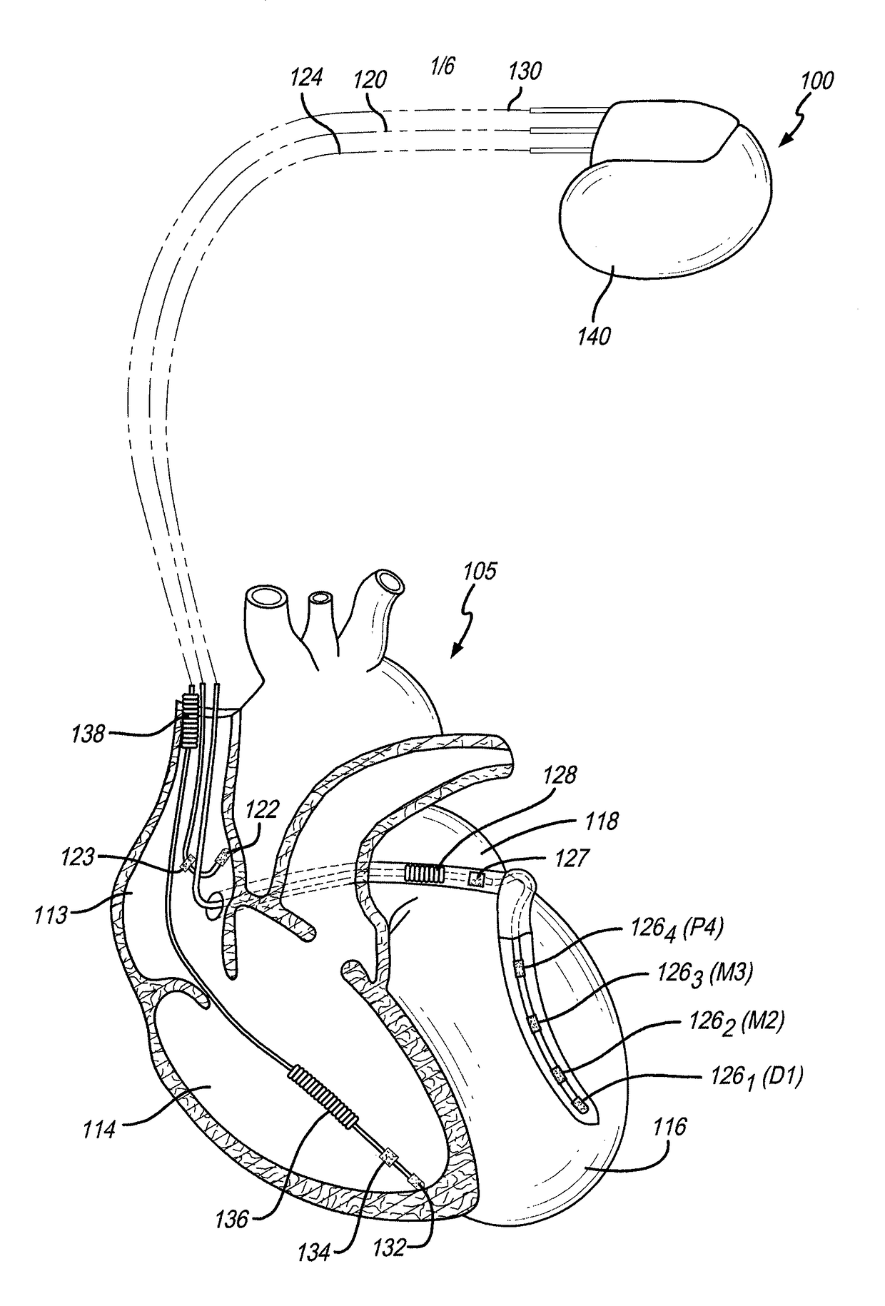
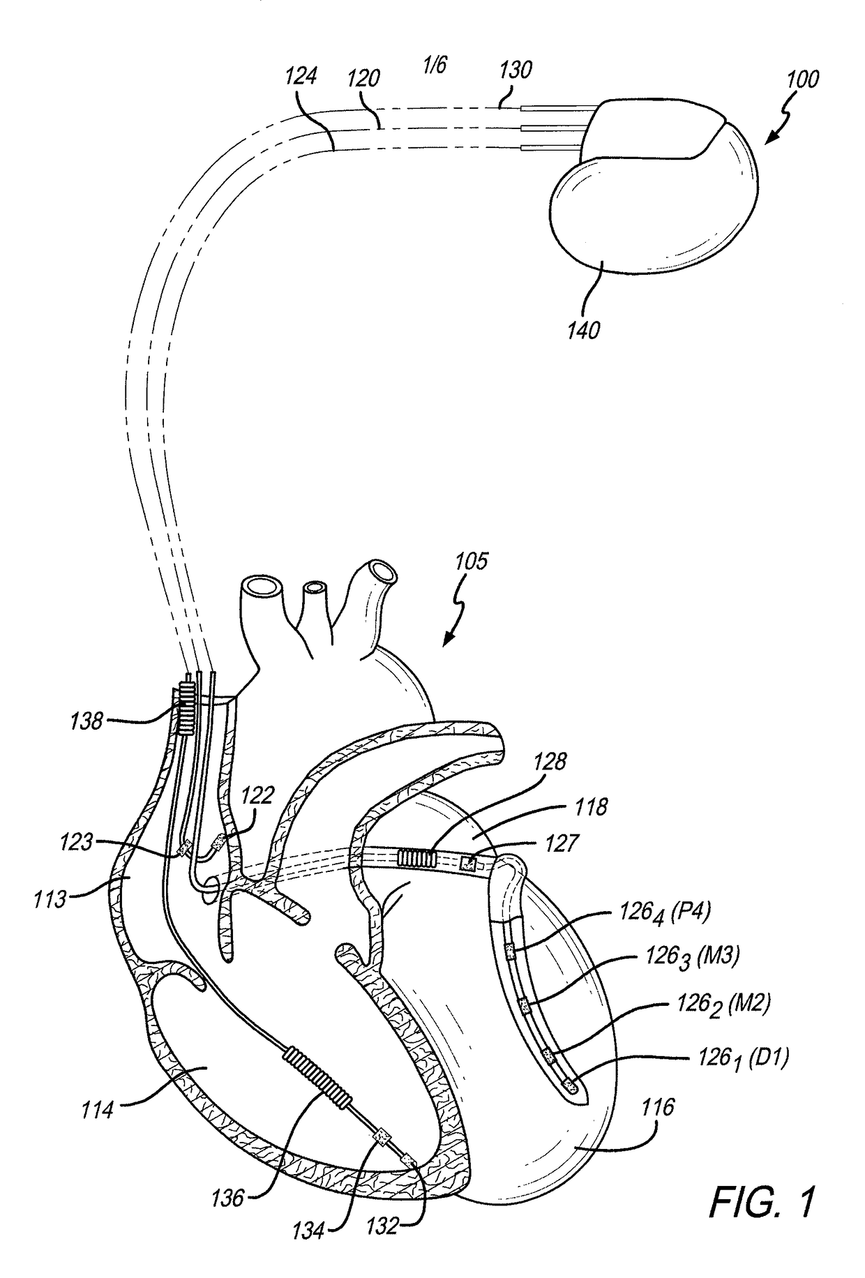
BACKGROUND OF THE INVENTION[0001]Embodiments of the present disclosure generally relate to methods and system that provide for automatic, adaptive, and programmable bi-ventricular fusion pacing.[0002]Implantable stimulation devices or cardiac pacemakers are a class of cardiac rhythm management devices that provide electrical stimulation in the form of pacing pulses to selected chambers of the heart. As the term is used herein, a pacemaker is any cardiac rhythm management device with a pacing functionality regardless of any additional functions it may perform, such as cardioversion / defibrillation.[0003]A pacemaker is comprised of two major components, a pulse generator and a lead. The pulse generator generates the pacing stimulation pulses and includes the electronic circuitry and the power cell or battery. The lead, or leads, is implanted within the heart and has electrodes which electrically couples the pacemaker to the desired heart chamber(s). A lead may provide both unipolar and...

Claims


Application Information

Patent Timeline
IPC IPC(8): A61N1/368A61N1/372A61N1/365
CPCA61N1/3684A61N1/3682A61N1/37247A61N1/37223A61N1/36542A61N1/36843A61N1/36842
Inventor WISNOSKEY, BRIAN
Owner PACESETTER INC
Why Eureka
Try Eureka