Installation for processing metal bars with improved means for transferring the bars, and method provided thereby

Inactive Publication Date: 2006-05-23
OSCAM
View PDF12 Cites 13 Cited by
  • Summary
  • Abstract
  • Description
  • Claims
  • Application Information

AI Technical Summary

Benefits of technology

[0005]The main object of the present invention is to provide an installation of the type specified at the outset which is simple and functional and which in particular is

Problems solved by technology

The same arrangement instead is not used, or usable, to transfer the bars still to be bent from a station upstream of the bending station to the bending station.
Because of this limitation, the known device therefore must provide a complex system for transferring the bars from the station upstream of the bending station, wh

Method used


Image

  • Installation for processing metal bars with improved means for transferring the bars, and method provided thereby
  • Installation for processing metal bars with improved means for transferring the bars, and method provided thereby
  • Installation for processing metal bars with improved means for transferring the bars, and method provided thereby

Examples


Example

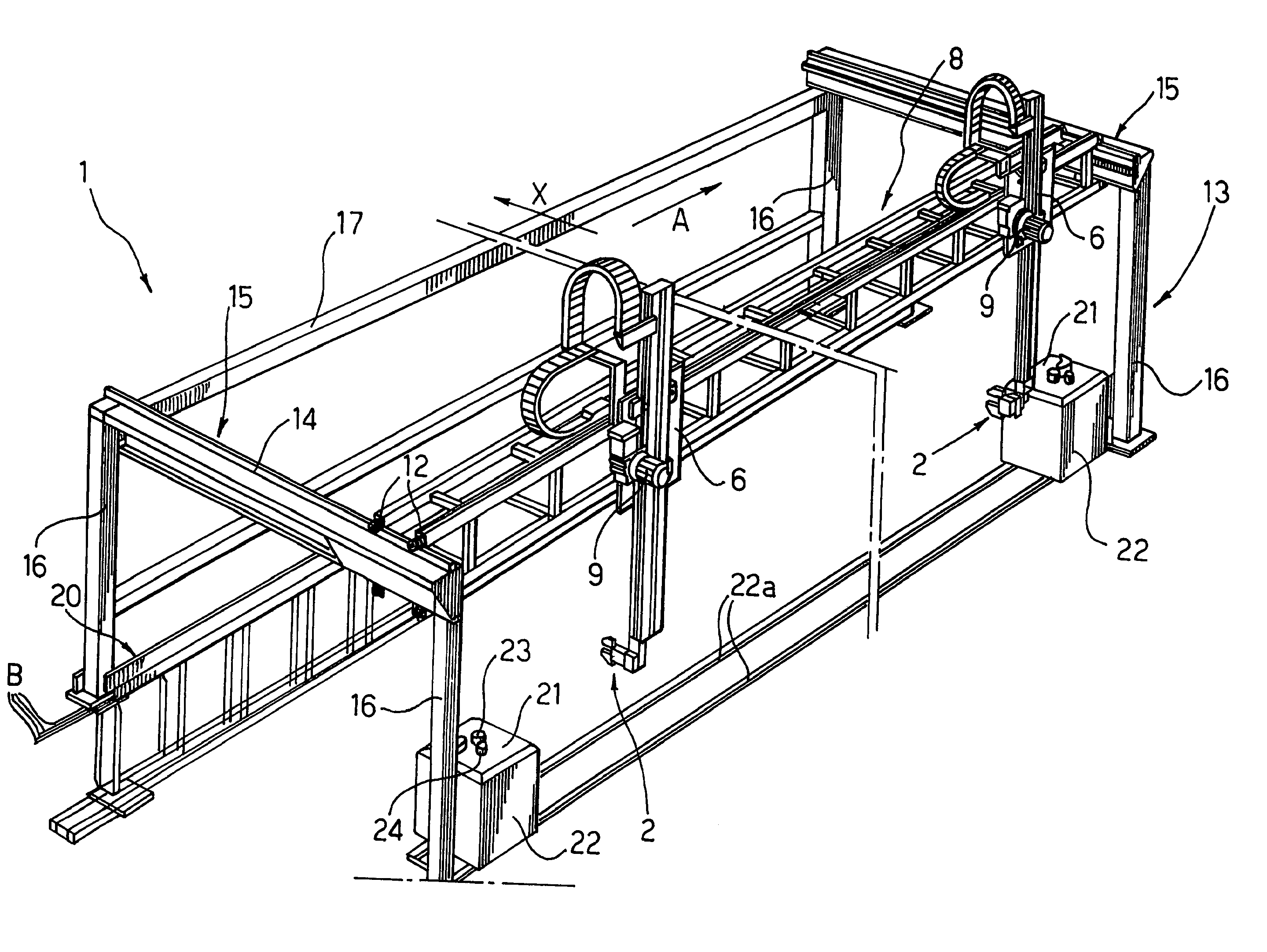
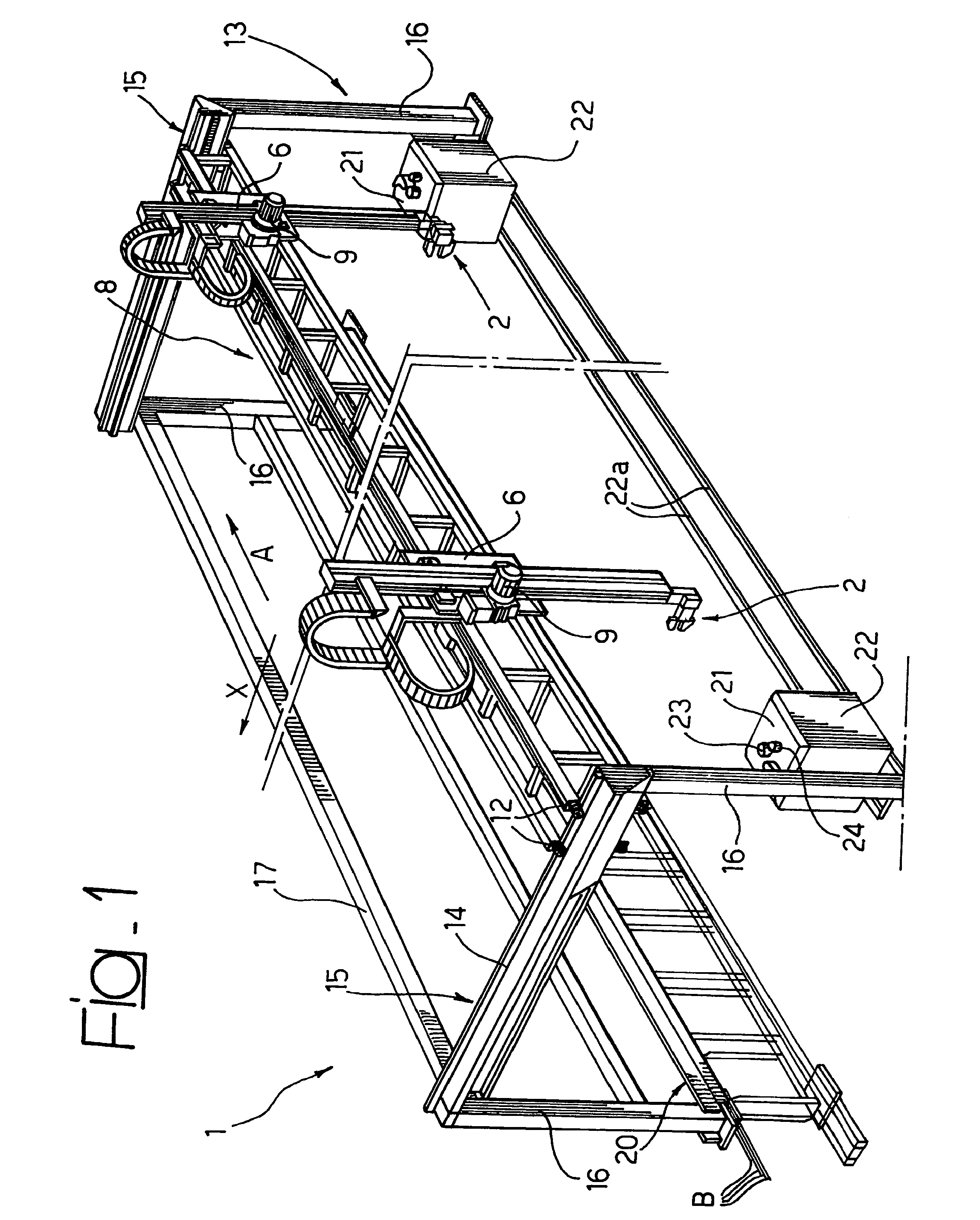
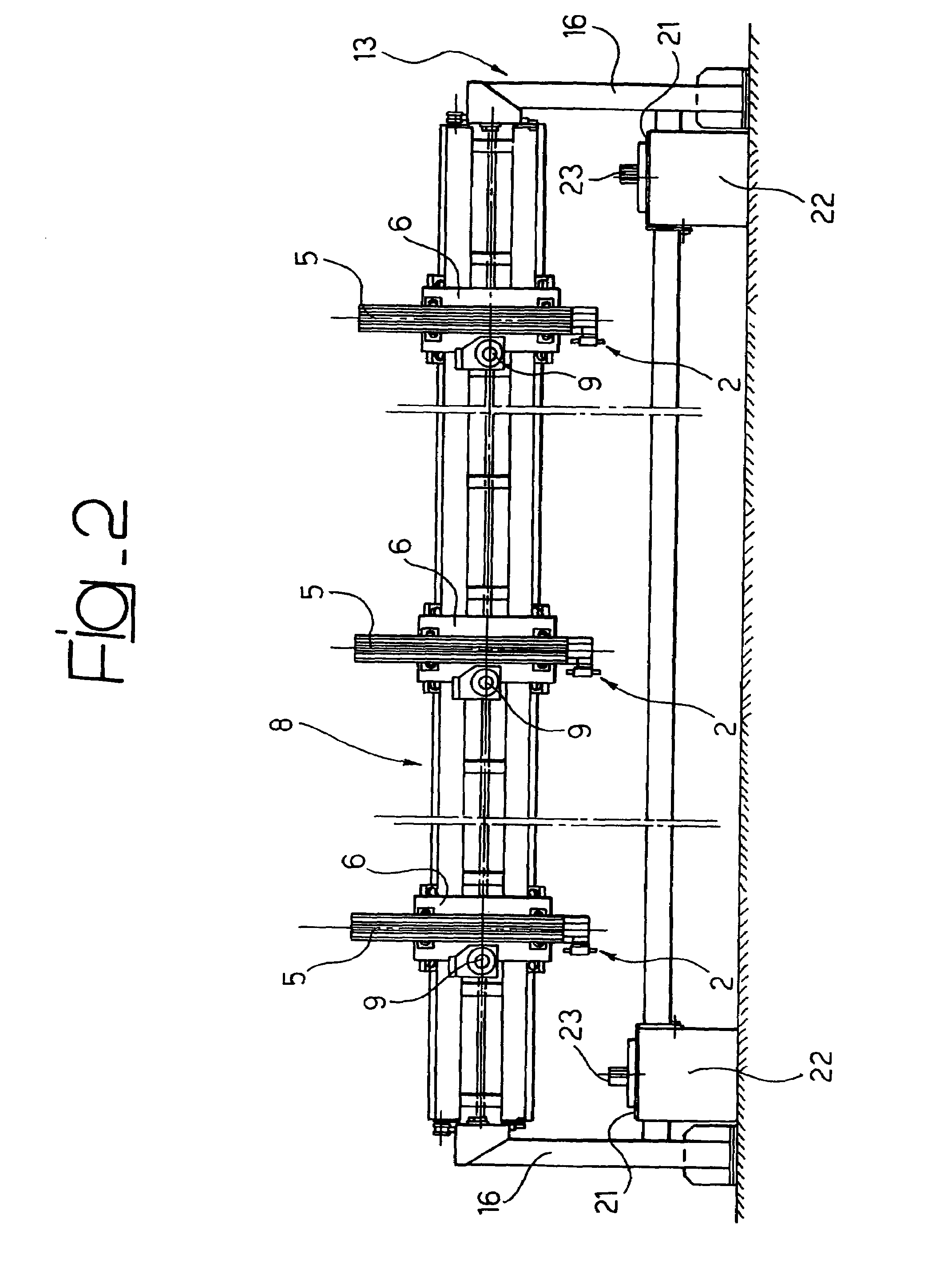
[0018]With reference to the drawings, the number 1 globally designates a device for transferring bars which, in the case of the illustrated example, comprises three grippers 2 (whereof only two are visible in FIG. 1). The three grippers 2 and the related actuation devices associated therewith are mutually identical, so that hereafter the structure and arrangement of only one of said pliers shall be described.

[0019]As FIG. 3 clearly shows, each set of pliers 2 (i.e. each gripper) is borne by an articulated wrist 3 which is articulated in 4 to the structure of a vertically movable slide 5. Thanks to the articulation 4, the pliers 2 can oscillate between two operative conditions, both visible in FIG. 3, angularly offset with respect to each other, in the case of the specific example shown, by an angle of about 90°. In both positions, the jaws of the pliers 2, designated as 2a, are able to grip the bars B keeping them parallel to each other and substantially coplanar. In the first opera...


PUM

PropertyMeasurementUnit
Diameteraaaaaaaaaa
Lengthaaaaaaaaaa

Abstract

A transferring device usable in installations for cutting and/or bending metal bars, particularly bars intended for concrete reinforcement. The device comprises one or more gripping pliers movable along mutually orthogonal axes of an overhead traveling crane arrangement. Each set of pliers is carried by an articulated wrist.

Description

BACKGROUND OF THE INVENTION[0001]The present invention relates to installations for cutting and / or bending metal bars.[0002]In particular, the invention relates to an installation for bending metal bars, particularly bars intended for concrete reinforcement, comprising the characteristics set out in the pre-characterising part of claim 1.[0003]An installation of the aforesaid kind is described and illustrated in the document WO 01 / 91936. This known installation is provided with transfer means comprising a plurality of pliers of the type specified above, each of which is borne by a slide movable vertically on a carriage which in turn is able to translate along a respective raised cross member. The raised cross members carrying the various pliers are mounted in sliding fashion in the form of overhead travelling cranes on raised longitudinal beams of a fixed support frame. This arrangement is used to transfer bars bent in a bending station from said bending station to a station for col...

Claims


Application Information

Patent Timeline
IPC IPC(8): B21D7/00B21D11/12B21D43/00
CPCB21D11/12B21F23/007B21D43/006
Inventor PERUZZO, LORENZOPERUZZO, STEFANO
Owner OSCAM
Why Eureka
Try Eureka