Sensor for Detecting the Amount of a Reducing Agent and the Amount of a Pollutant in an Exhaust Gas

Active Publication Date: 2012-03-08
BAYERISCHE MOTOREN WERKE AG
View PDF2 Cites 5 Cited by
  • Summary
  • Abstract
  • Description
  • Claims
  • Application Information

AI Technical Summary

Benefits of technology

[0015]According to one aspect of the invention, it is particularly advantageous to completely remove one of the constituents from the exhaust gas after the first measurement, so that, during the second measurement, the unfiltered constituent can be inferred directly from the measuring signal after the filtering, and only a single computation will be required for determining the filtered constituent.
[0016]The invention also provides an arrangement for the selective catalytic reduction of pollutants in an exhaust gas, having a system assembly according to the invention for detecting the amount of pollutant and the amount of reducing agent in the exhaust gas at the output of the arrangement. The arrangement has an injection mechanism which is provided for injecting the reducing agent into the exhaust gas at the input of the arrangement based on a dosing amount as a function of the measuring signals of the sensor. The arrangement further has a catalyst which is provided for reducing the pollutants in the exhaust gas based on the reducing agent. Since the system assembly according to the invention separately outputs the amount of pollutant and of reducing agents in the exhaust gas, the pollutant fraction in the exhaust gas cannot only be adjusted directly, the control can also take place in the state of equilibrium of the overall system. Thus, an optimal dosing of the reducing agent is possible for a maximal reduction of the pollutants without having to provide intrusive control.
[0017]The measured reducing agent fraction in the exhaust gas and, therefore, the computed optimal dosing of th

Problems solved by technology

However, if the reducing agent dose is too low, pollutants will remain in the exhaust gas after the reaction.
If it is too high, reducing agent will remain in the exhaust gas, which is also undesirable because ammonia, for example, is also harmful to health and the environment.
Since the amount of pollutant in the exhaust gas cannot be determined directly, the control of the

Method used


Image

  • Sensor for Detecting the Amount of a Reducing Agent and the Amount of a Pollutant in an Exhaust Gas
  • Sensor for Detecting the Amount of a Reducing Agent and the Amount of a Pollutant in an Exhaust Gas

Examples


Example

DETAILED DESCRIPTION OF THE DRAWING

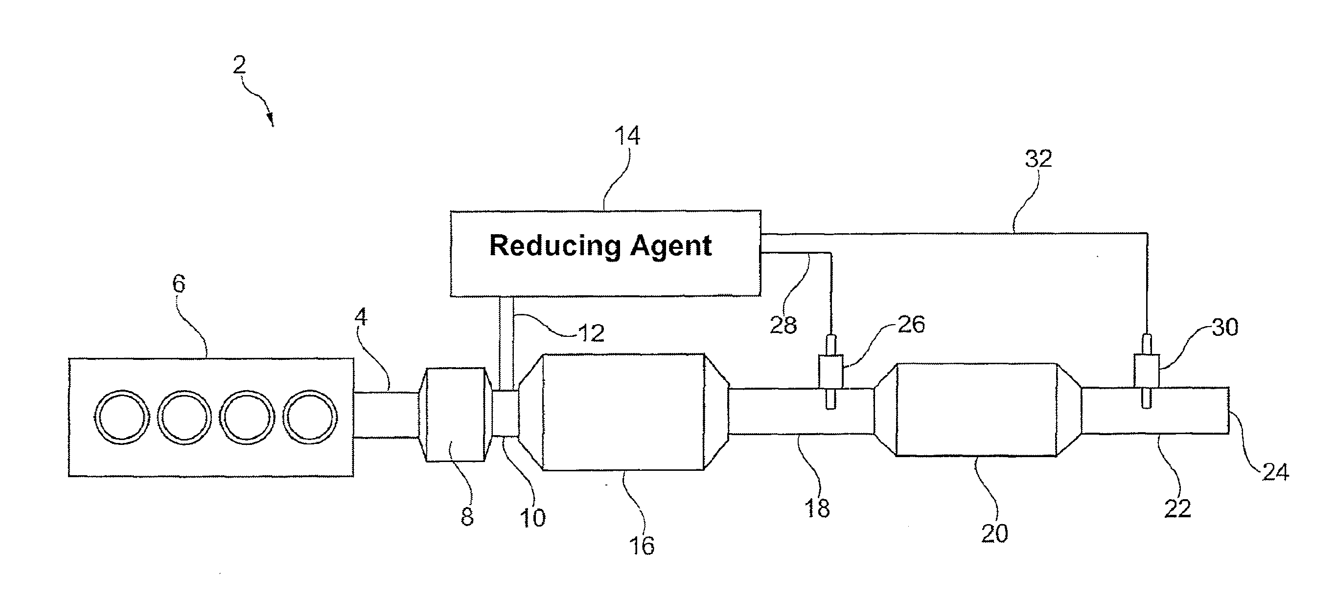
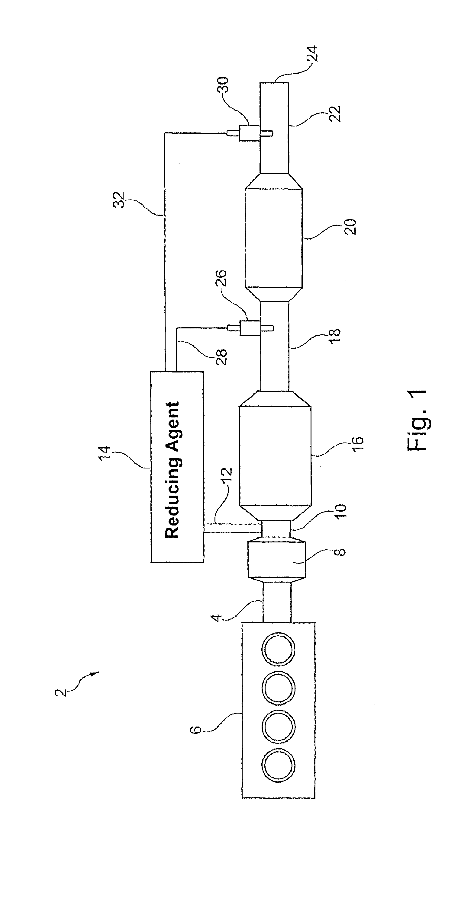
[0028]In FIG. 1, an embodiment of an exhaust gas aftertreatment system 2 is shown. The aftertreatment system 2 is suitable for minimizing the nitrogen oxide fraction in the engine exhaust gas 4 from an engine 6. The engine exhaust gas 4 is fed to a diesel oxidation catalyst 8, in which hydrocarbon compounds and carbon monoxide from the engine exhaust gas are afterburnt. The prepurified engine exhaust gas 10 from the diesel oxidation catalyst 8 is enriched with ammonia 12 from a dosing apparatus 14 to be described below, and is subjected to a selective catalytic reduction 16. In this case, nitrogen oxides in the prepurified engine gas 10 and the ammonia react with one another and convert to nitrogen and water. A diesel particulate filter 20 filters the remaining ammonia 12 from the thus purified engine exhaust gas 18 and emits the filtered exhaust gas 22 to the atmosphere (ambient air) 24.

[0029]According to one embodiment of the invention, a first n...


PUM


Abstract

A system assembly detects the amount of reducing agent and the amount of pollutant in an exhaust gas. The system assembly has a first pollutant sensor, which is cross-sensitive to the reducing agent, and is provided for emitting a first measuring signal proportional to the amount of pollutant in the exhaust gas for use in front of a filtering device for the selective reducing of the reducing agent or the pollutant in the exhaust gas. A second pollutant sensor, which is also cross-sensitive to the reducing agent, emits a second measuring signal proportional to the amount of pollutant in the exhaust gas for use behind the filtering device.

Description

CROSS-REFERENCE TO RELATED APPLICATIONS[0001]This application is a continuation of PCT International Application No. PCT / EP2010 / 055812, filed Apr. 29, 2010, which claims priority under 35 U.S.C. §119 from German Patent Application No. DE 10 2009 022 882.9, filed May 27, 2009, the entire disclosures of which are herein expressly incorporated by reference.BACKGROUND AND SUMMARY OF THE INVENTION[0002]The invention relates to a system assembly for detecting the amount of a reducing agent, such as ammonia, and the amount of a pollutant, such as nitrogen oxide, in an exhaust gas, to an arrangement for the selective catalytic reduction of pollutants in an exhaust gas, to an exhaust gas aftertreatment system and to a process for detecting the amount of reducing agent and the amount of pollutant in an exhaust gas.[0003]Exhaust gases resulting from the fuel combustion in a vehicle have to be aftertreated for minimizing the pollutant emission. For example, the emission of nitrogen oxides is to...

Claims


Application Information

Patent Timeline
IPC IPC(8): F01N9/00G01N33/00
CPCF01N3/035F01N3/208Y02T10/24F01N2900/14F01N2560/026Y02T10/12
Inventor AICHHORN, BERNHARD
Owner BAYERISCHE MOTOREN WERKE AG
Why Eureka
Try Eureka