
Eureka
For R&D, Eureka makes reading and utilizing patents & technical documents easy.
Eureka AIR
Designed for self-driven R&D workflows. Generate viable solutions, solve complex R&D challenges, empower your innovation with AI.

Eureka Materials
Designed for material experts only. Revolutionize your material R&D, from search, analyze, to developing new materials.

TechResearch
Generate reliable direction feasibility study reports for your R&D in just a few steps.

TechSeek
Discover and master advanced knowledge NOW. Basics, ideas, possibilities, all at once.

TechMind
As an expert in R&D Theories, TechMind can generates customized viable solutions instantly.

TechRisk
Analyze your overall solution with one click, know your potential R&D risks in advance.

TechMonitor
Get weekly tech updates, stay abreast of the latest tech innovations and key insights.
Image forming apparatus which controls transferring timing to the paper according to a change of process speed
- Summary
- Abstract
- Description
- Claims
- Application Information
AI Technical Summary
Benefits of technology
Problems solved by technology
Method used
Image

Examples
first embodiment
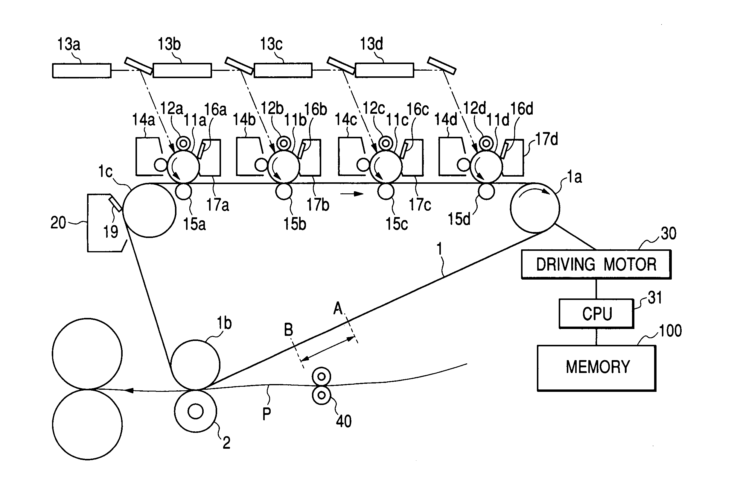
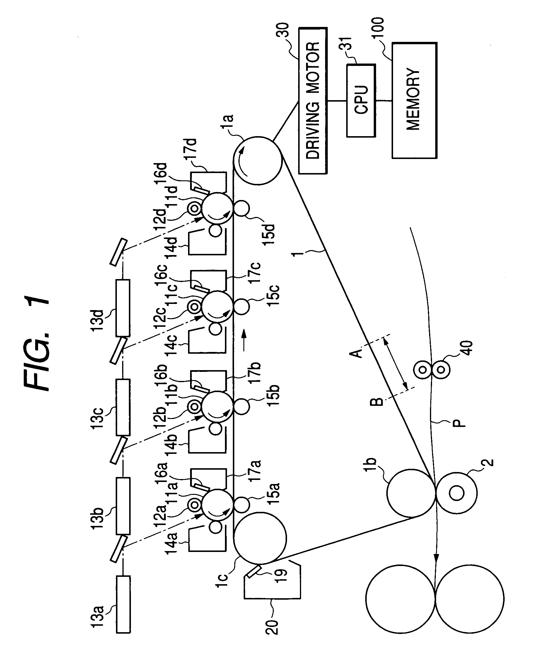
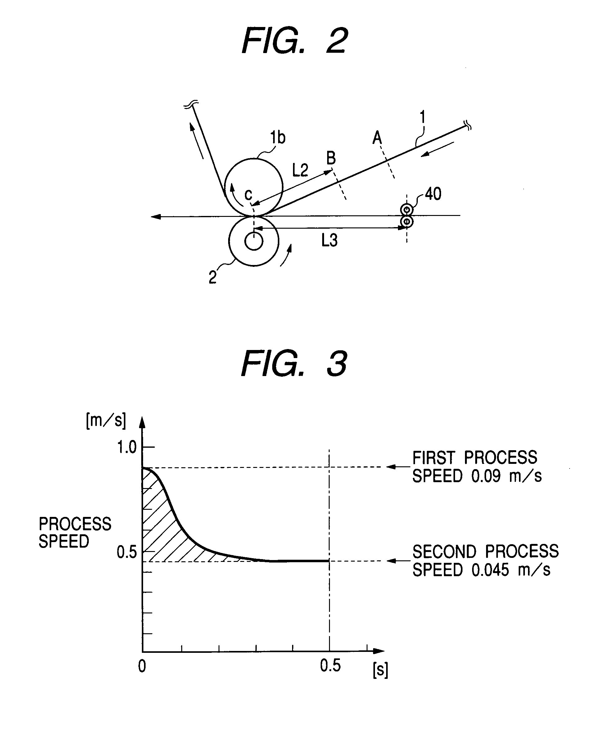
[0034]FIG. 1 is a sectional view showing a schematic structure of a “color image forming apparatus” according to the first embodiment FIG. 2 is a sectional view showing a structure around a secondary transfer nip area.
[0035]This structure has photosensitive drums 11a to 11d corresponding to color toners of a first color of yellow, a second color of magenta, a third color of cyan, and a fourth color of black, respectively. An intermediate transfer belt 1 serving as an intermediate transfer member is in contact with the photosensitive drums 11a to 11d in primary transfer units thereof, respectively.
[0036]The photosensitive drums are arranged along a moving direction of the intermediate transfer belt 1 in the following order from the upstream side: the photosensitive drum 11a of the first color (yellow), the photosensitive drum 11b of the second color (magenta) located closest to the photosensitive drum 11a on the downstream side thereof, the photosensitive drum 11c of the third color ...
second embodiment
[0086]FIG. 4 is a sectional view showing a schematic structure of a “color image forming apparatus” according to a second embodiment. Components identical with those in FIG. 1 are denoted by identical reference numerals and symbols and will not be described again. This embodiment is an example in which, at the time of initial rotation, a pattern for detecting a conveying speed of a belt is formed on the intermediate transfer belt 1, a conveying speed of the intermediate transfer belt 1 is detected by a sensor for concentration detection 32 opposed to the drive roller 1a, a building-down amount of a process speed is calculated, paper feeding timing is calculated, a calculated timing value is stored in storing means, and paper feeding timing is determined on the basis of the stored value at the time of image formation.
[0087]An operation of this embodiment will be hereinafter described more in detail.
[0088]At the time of initial rotation such as the time of input of a power supply, the...
third embodiment
[0096]An “image forming apparatus,” according to a third embodiment will be described. This embodiment is an example in which the image forming apparatus has, in addition to a second process speed for coping with cardboard, rough paper, and the like, a third process speed for coping with other media such as an OHT. Since a schematic structure of this embodiment is the same as the first embodiment, FIG. 1 and the description of FIG. 1 are applied, and the structure will not be described here.
[0097]In this embodiment, a process speed at the time of normal image formation (first process speed) is set to 0.09 m / s, and the second process speed is set to 0.045 m / s, which is half the first process speed, as a cardboard and rough paper mode. In addition, the third process speed is set to 0.03 m / s, which is ⅓ the process speed at the time of normal image formation (first process speed), as an OHT mode.
[0098]FIG. 5 is a graph showing a process speed of the intermediate transfer belt 1 with re...
PUM
 Abstract
Description
Claims
Application Information
 - R&D Engineer
- R&D Manager
- IP Professional
- Industry Leading Data Capabilities
- Powerful AI technology
- Patent DNA Extraction
Browse by: Latest US Patents, China's latest patents, Technical Efficacy Thesaurus, Application Domain, Technology Topic, Popular Technical Reports.
© 2024 PatSnap. All rights reserved.Legal|Privacy policy|Modern Slavery Act Transparency Statement|Sitemap|About US| Contact US: help@patsnap.com