Net rucking apparatus and method

a technology of net rucking and netting tube, which is applied in mechanical equipment, manufacturing tools, transportation and packaging, etc., can solve the problems of limiting the amount of netting that can be rucked onto the netting tube, displacing equipment prospective purchasers, and not particularly neatly shirred netting tube,

Active Publication Date: 2006-05-30
POLY CLIP SYST
View PDF25 Cites 37 Cited by
  • Summary
  • Abstract
  • Description
  • Claims
  • Application Information

AI Technical Summary

Benefits of technology

[0008]The present invention is an improvement to the prior art comprising placing a coaxial ring between the netting tube and the second tube, a distance from the bottom end of the second tube, creating an annular space defined by the netting tube, the ring, and the second tube. The netting curls underneath the second tube and fills this annular space first. On the next stroke, netting is shirred over the netting that had been shirred into this annular space. This method causes the netting to be shirred neatly, in multiple layers, without waviness, and allows more netting to be shirred onto a given length of netting tube.

Problems solved by technology

However, the netting is not shirred particularly neatly by this method.
The generally unkempt appearance of the netting on the tube is displeasing to prospective purchasers of the equipment.
Additionally, and more importantly, the lack of neatness, caused as it is by a lack of uniformity, prevents shirring as much netting onto the tube as may be hoped for.
These newly-developed net deruckers require a clear space on the end of the netting tube, a space greater than the length of sausages to be made, further limiting the amount of netting that can be rucked onto the netting tube.
(Please note that more netting can be rucked onto a netting tube simply by increasing the size of the netting tube, but this option is not available or, at best, is impractical, for users with limited space.)

Method used


Image

  • Net rucking apparatus and method
  • Net rucking apparatus and method
  • Net rucking apparatus and method

Examples


Embodiment Construction

[0019]The organization and manner of the preferred embodiments of the invention, together with further objects and advantages thereof, may best be understood by reference to the following description of the preferred embodiment of the invention, taken in connection with the following drawings:

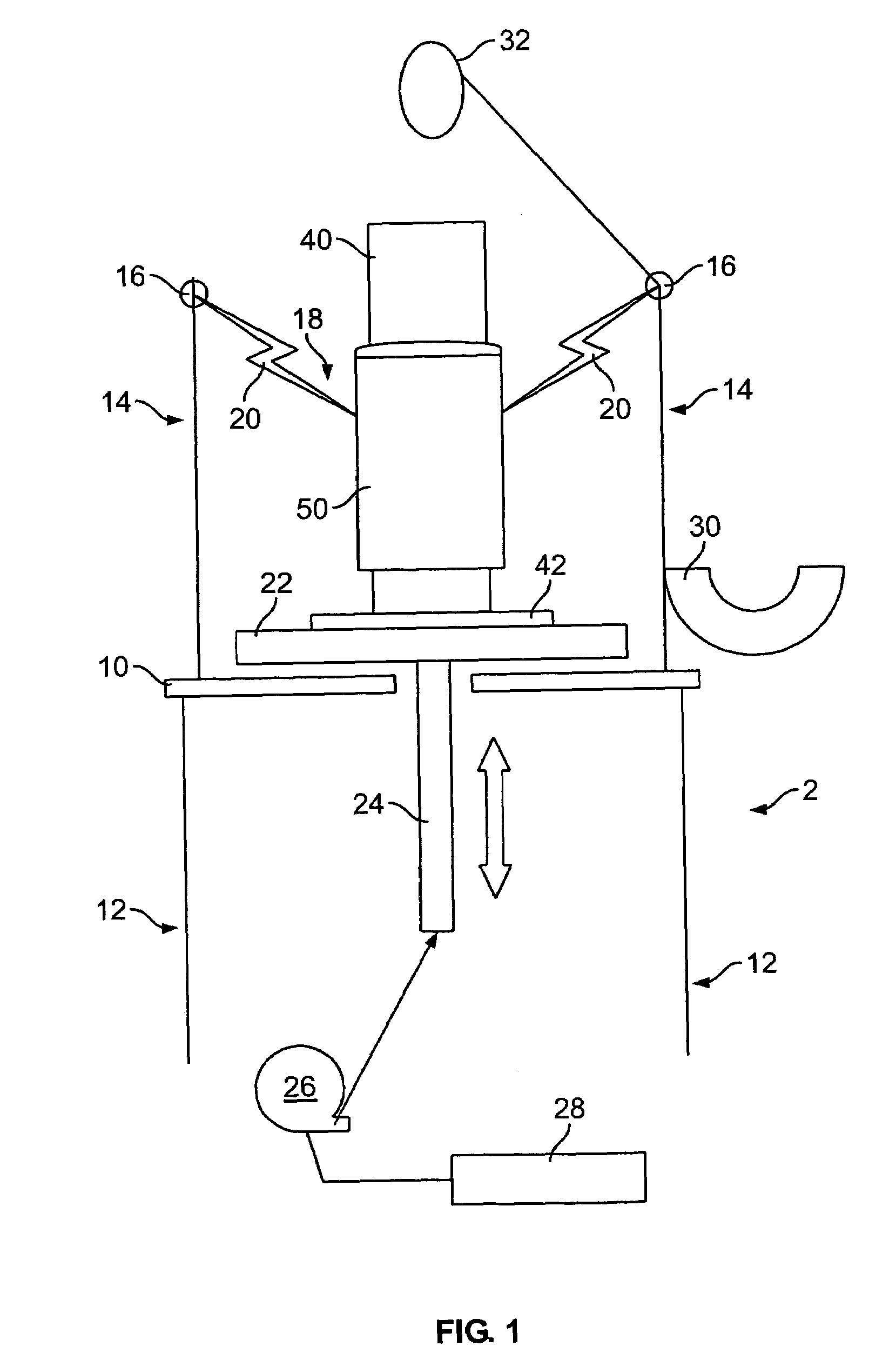
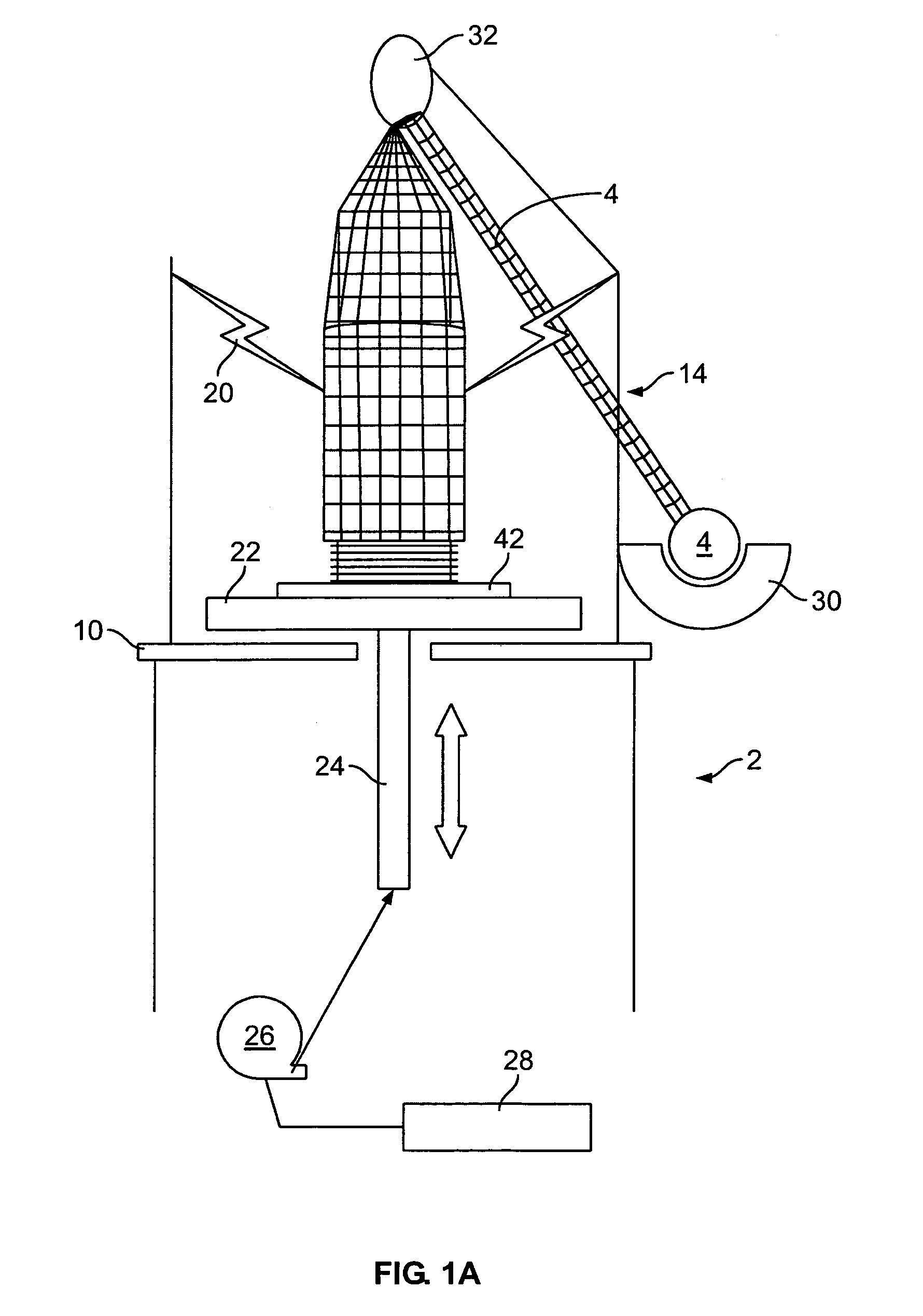
[0020]The preferred embodiment of the net rucking apparatus 2, is shown in elevation view in FIG. 1 without the netting 4 present, and in FIG. 1A with the netting 4 present. The apparatus 2 comprises a frame 10, a netting tube 40, and a second tube 50. The frame 10 has legs 12 to support it, and upper arms 14 that hold a net rucker head 16. The net rucker head 16 defines a passage 18 through which the netting tube 40 and second tube 50 pass. Attached to the net rucker head 16 and extending into the passage 18 are a plurality of spring-loaded fingers 20.

[0021]A moveable platform 22 sits on top of the frame 10. It is configured to travel in an upward and downward direction, powered by lifting mea...


PUM

PropertyMeasurementUnit
distanceaaaaaaaaaa
diameteraaaaaaaaaa
reciprocating movementaaaaaaaaaa

Abstract

An apparatus and method for shirring netting onto a netting tube. A second tube is placed over and coaxially to the netting tube and netting is stretched over the second tube. The two tubes are caused to move in a reciprocating manner through a plurality of spring-loaded fingers, which allow the netting to pass on the downstroke and hold the netting on the upstroke. As the two tubes move, the netting is pulled over the second tube and shirred onto the netting tube. An annular space formed by a tube ring placed between the netting tube and the second tube causes the netting to shir in multiple, neatly aligned layers.

Description

BACKGROUND OF THE INVENTION[0001]This invention relates to the field of preparing food products in shirred, tubular casings and enclosing the products in a netting. One method generally used in the industry is to pump food products, such as sausage meat, whole muscle meats, or otherwise, through a product horn. The meat products are forced into an edible film and then into netting. The food products to be packaged will expand and push the film through the netting. After processing, such as smoking or cooking, the netting will be removed, leaving a dimpled appearance on the food products that is considered pleasing to consumers. The edible casing will prevent the netting from sticking to the meat, so upon removal of the netting a clean appearance of the meat is maintained. (There is no reason why the invention is limited to meat; it can be used for cheese or vegetarian sausage or anything else for which a dimpled appearance is desired.) This method is illustrated in U.S. Pat. No. 4,9...

Claims


Application Information

Patent Timeline
Patent Type & Authority Patents(United States)
IPC IPC(8): B23P19/04A22C13/02
CPCA22C13/02B65B9/18Y10T29/53657Y10T29/49879Y10T29/49838A22C2013/026
Inventor PINTO, ROBERTHASCHKE, EGGO
Owner POLY CLIP SYST
Why Eureka
Try Eureka