Brace for concrete forms

a concrete form and brace technology, applied in the field of concrete construction materials, can solve the problems of prior steel braces, hinder the removal of nails used to secure wooden blocks, and wooden blocks are typically sawn into triangular shapes, so as to add strength to the brace, and lend strength and durability

Inactive Publication Date: 2006-05-30
DAYTON SUPERIOR CORP
View PDF47 Cites 44 Cited by
  • Summary
  • Abstract
  • Description
  • Claims
  • Application Information

AI Technical Summary

Benefits of technology

[0006]The present invention provides an improved brace for securing the form members of a concrete form to a casting surface. The brace can be molded from plastic and includes truss reinforcing elements which lend strength and durability to the brace. In an exemplary embodiment, first and second leg members of the brace are joined at one end and are spaced apart to form

Problems solved by technology

The wooden blocks are typically saw cut into a triangular shape and are not always dimensionally uniform.
These wooden blocks are usually damaged upon removal from the concrete forms, thereby hindering the removal of nails used to secure the wooden b

Method used


Image

  • Brace for concrete forms
  • Brace for concrete forms
  • Brace for concrete forms

Examples


Embodiment Construction

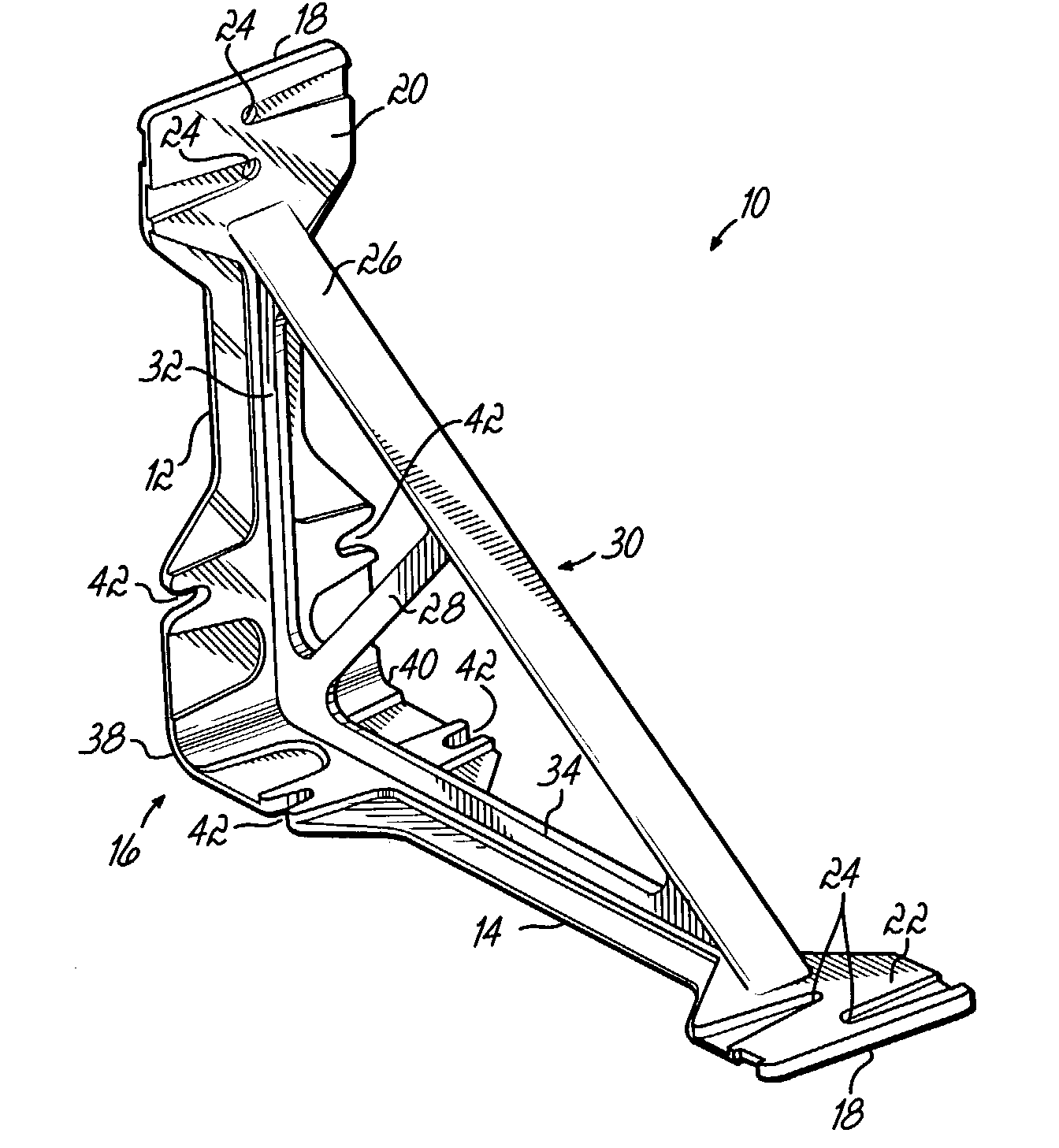
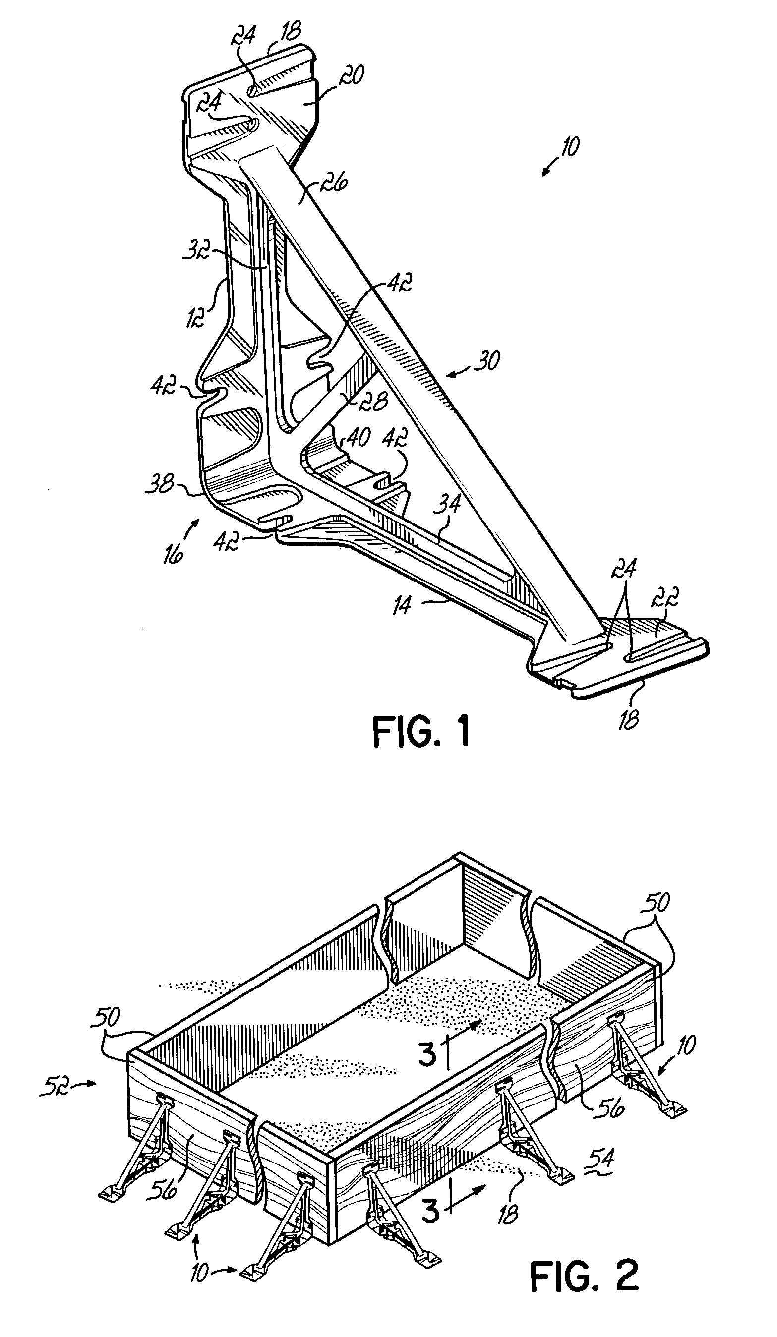
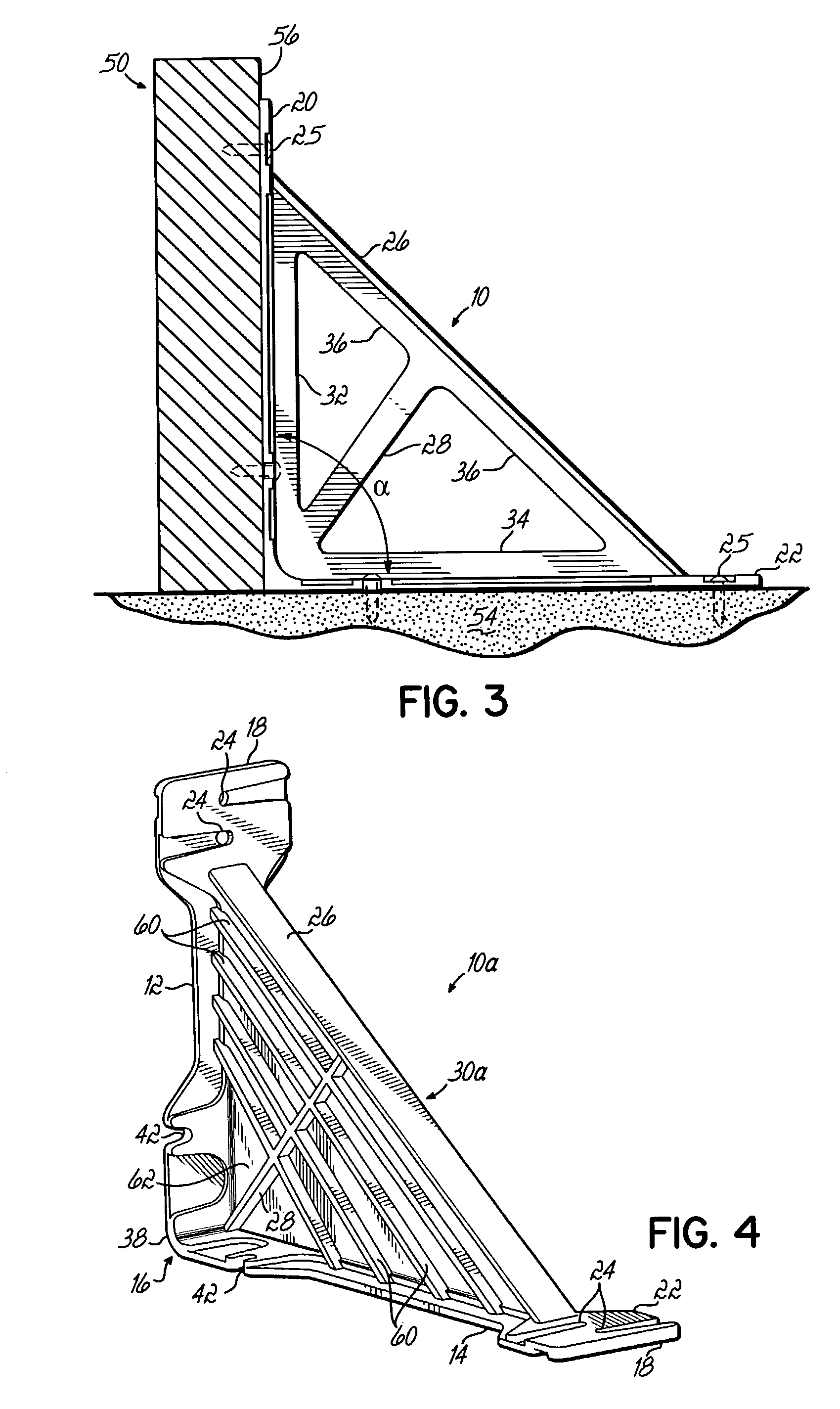
[0019]Referring to FIGS. 1–3, there is shown an exemplary brace 10 of the present invention. Brace 10 includes first and second leg members 12, 14, joined at first ends 16 of the leg members 12, 14 and spaced from one another to form an angle ∝. The second ends 18 of the leg members 12, 14 have enlarged portions 20, 22 with apertures 24 sized to receive fasteners 25 whereby the first leg member 12 may be positioned adjacent an outer surface of a concrete form 52 and the second leg member may be positioned adjacent a casting surface 54 for creating a concrete wall panel. The brace 10 further includes a bridging member 26 which extends between the second ends 18 of the first and second leg members 12, 14 to add durability to the brace 10. A strut 28 extends between the joined, first ends 16 of the leg members 12, 14 and an intermediate portion of the bridging member 26, whereby the bridging member 26 and the strut 28 form a truss section 30 of the brace 10. First and second raised rib...


PUM


Abstract

A brace for securing concrete form members to a casting surface. First and second leg members are spaced to form an angle. A bridging member extends between opposing ends of the leg members and a strut extends between the joined ends of the leg members and the bridging member. The bridging member and strut form a truss, together with raised ribs along the legs and bridging member. The brace may be molded from plastic as a one-piece structure.

Description

CROSS REFERENCE TO RELATED APPLICATION[0001]Pursuant to 37 C.F.R. § 1.78(a)(4), this application claims the benefit of and priority to prior filed Provisional Application Ser. No. 60 / 394,502, filed Jul. 9, 2002, now abandoned which is expressly incorporated herein by reference.FIELD OF THE INVENTION[0002]This invention relates to concrete construction materials, and more particularly to a brace for securing concrete forms to a casting surface.BACKGROUND OF THE INVENTION[0003]Concrete wall panels are conventionally used in the construction of industrial buildings and other structures. In general, individual concrete wall panels are formed at the construction site by pouring concrete into forms which have been assembled on a casting surface, such as the floor of the building where the wall panels will be used. The concrete forms are typically secured to the casting surface by braces which hold the forms in place until the concrete wall panel has cured. The concrete forms are typically...

Claims


Application Information

Patent Timeline
IPC IPC(8): E04G17/00E04G13/00E04G17/14
CPCE04G17/14E04G13/00E04B2001/405E04B2001/389
Inventor SHAWLEE, KENNETHLANCIAL, MARTIN E.GILNER, JOHNBENNETT, CLIFFORD D.
Owner DAYTON SUPERIOR CORP
Why Eureka
Try Eureka