Multiple cutting edge rotary tool

a rotary tool and multi-edge technology, applied in the direction of turning tools, milling equipment, reaming tools, etc., can solve the problem of clearly prestressing the inter-cutting tips

Inactive Publication Date: 2006-05-30
JOHNE & PRAZISIONSWERKEUGE
View PDF26 Cites 7 Cited by
  • Summary
  • Abstract
  • Description
  • Claims
  • Application Information

AI Technical Summary

Benefits of technology

[0027]The problem and the advantage of the present invention are explained

Problems solved by technology

Apart from the specific problem of accommodating the multiplicity of cutting tips with such a parallel spring arrangement on the circu

Method used


Image

  • Multiple cutting edge rotary tool
  • Multiple cutting edge rotary tool
  • Multiple cutting edge rotary tool

Examples


Embodiment Construction

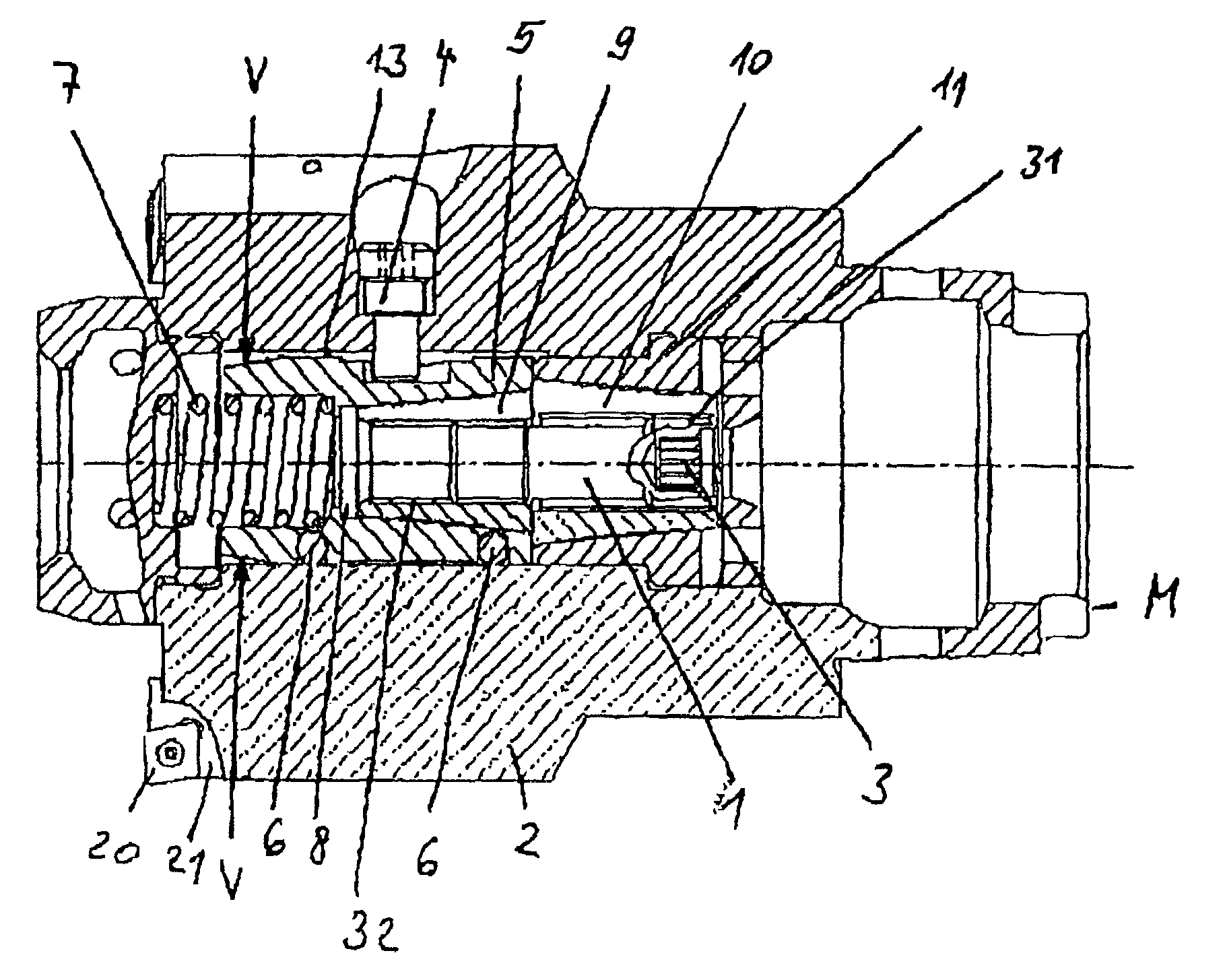
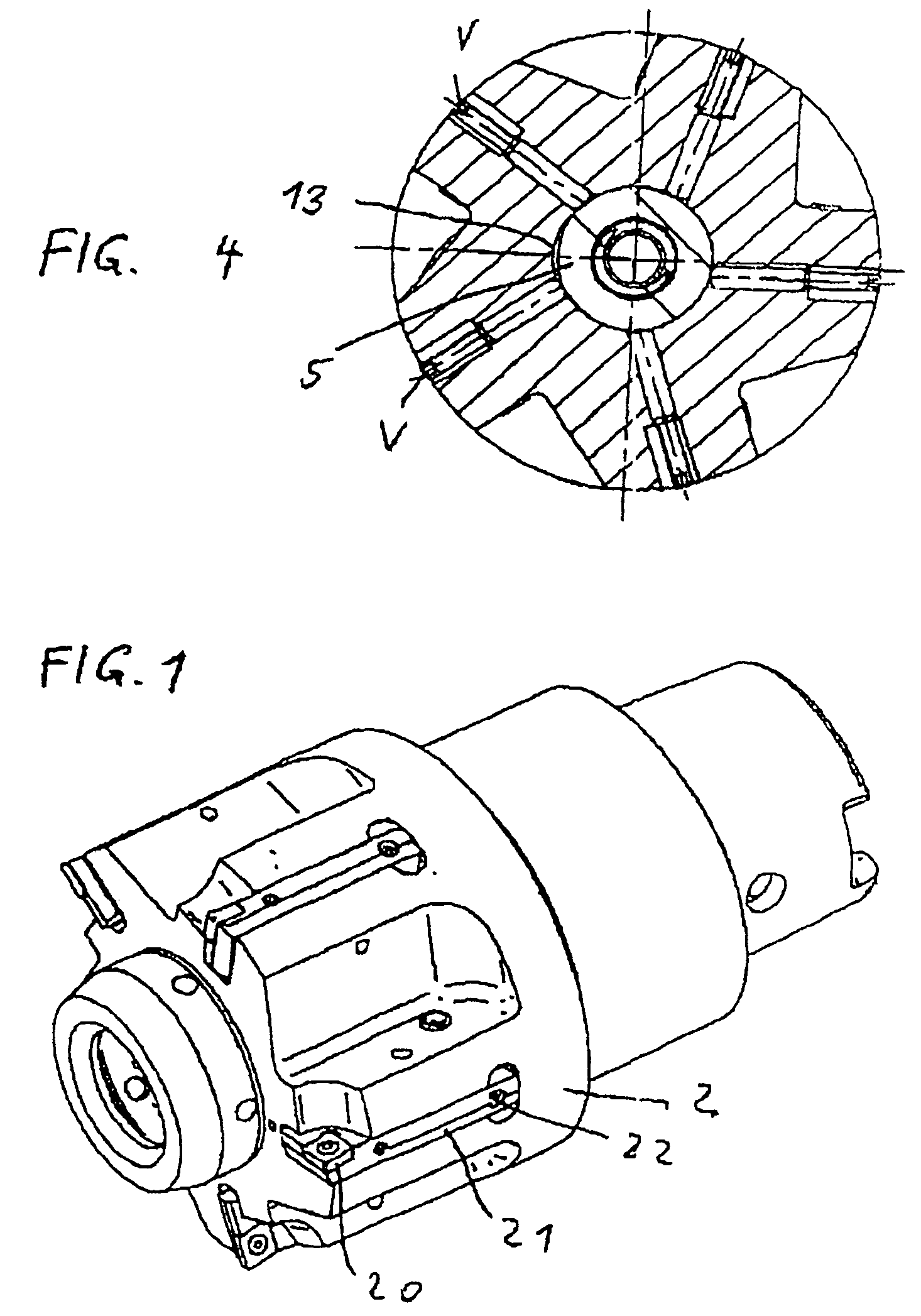
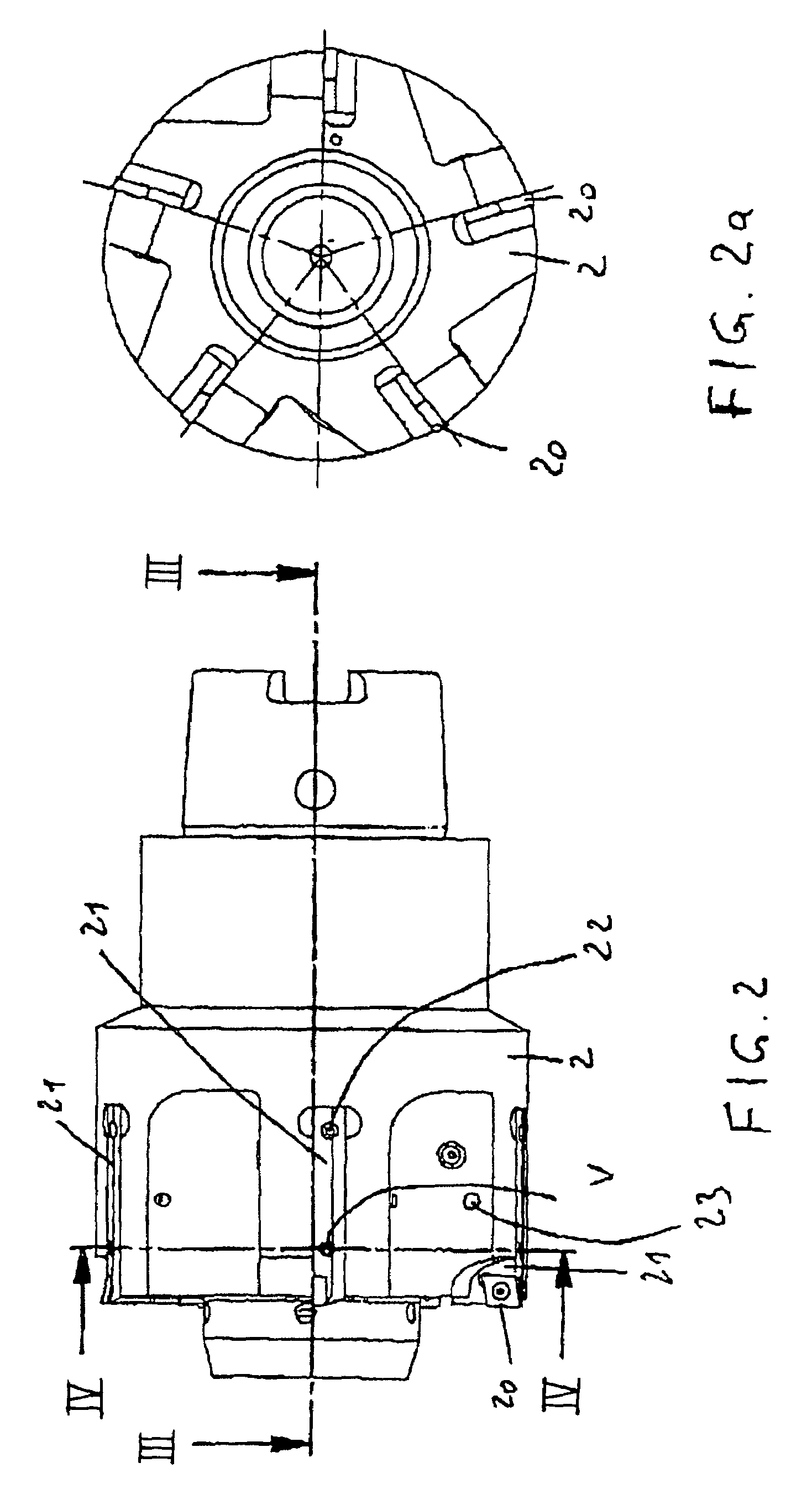
[0036]FIGS. 1, 2, 2a, 3, and 4 show a first embodiment of a multi-edged rotary tool according to the invention. Arranged in a tool head 2 is a differential screw 1 which, via a multiple-spline groove 3 in which the spindle of a machine M engages via a servomotor, is axially adjustable in a rotational manner and in the process engages by means of threads 31 and 32 in complementary threads in taper sleeves 9, 10 (FIG. 3). The threads 31, 32 have different pitches, so that the sleeve 5, which can only move axially on account of driving pin 4, is ultimately displaced against the pressure of a spring 7. At the same time, the differential screw 1 is supported in a sleeve 11 via a sleeve 10, 50 that the taper sleeve 9 and thus sleeve 5 are displaced axially forward or rearward depending on the direction of rotation of the servomotor. The maximum deflection of the spring 7 is shown in FIG. 3, the taper sleeves 9 and 10 bearing against one another at this maximum deflection. During the displ...


PUM

PropertyMeasurementUnit
Pressureaaaaaaaaaa

Abstract

The invention relates to a multiple cutting edge rotary tool having a radial individual adjustment of each cutting edge or having a central adjustment for all cutting edges together. The multiple cutting edge rotary tool used for machining has a number of holders that have, in the front part, cavities for accommodating cutting plates and have, in the area between their ends, a hole for passing through a fixing device with which each holder can be fixed to a support. The holder, on its portion that supports the cutting plate, can be elastically deflected in relation to a support by means of an adjusting device. In addition, the holder is provided with an opening and forms a parallel spiral spring arrangement whereby the cutting plate, during its adjustment, is essentially subjected to a parallel displacement with regard to the cutting edge. The adjusting device is provided in the form of a central adjusting screw which, as an axially adjustable differential screw, retains, by means of a lifting motion of the differential screw, the holder in a manner that permits it to be radially displaced in relation to its support and without play. The retention of said holder is effected by adjustable pressure pieces that are supported on parts of the adjusting screw.

Description

PRIORITY CLAIM[0001]This is a U.S. national stage of application No. PCT / EP02 / 08896, filed on 8 Aug. 2002. Priority is claimed on that application and on the following application(s): Country: Germany, Application No.: 101 39 064.5, Filed: 8 Aug. 2001.BACKGROUND OF THE INVENTION[0002]1. Field of the Invention[0003]The invention relates to a multi-edged rotary tool with individual adjustment in a radial direction of each cutting tip or with central adjustment for all the cutting tips together.[0004]2. Description of the Prior Art[0005]DE 198 27 778 A1 discloses a rotary tool in which a cutting tip can be radially adjusted in a sensitive manner on a parallel spring by means of an adjusting screw without a stick-slip effect.[0006]The tool is conceived as a single cutter; a plurality of cutting tips may be arranged one behind the other on a carrier. It can be used in particular for small bores.[0007]Such a tool constitutes a unit of small construction. Its dimensions can be selected in ...

Claims


Application Information

Patent Timeline
IPC IPC(8): B23B29/03B23C5/06B23C5/24
CPCB23C5/06B23C5/2472Y10T408/85843Y10T408/85895Y10T408/85892Y10T82/125B23B29/03446B23B29/03457B23B2260/056
Inventor JOHNE, FRANK
Owner JOHNE & PRAZISIONSWERKEUGE
Why Eureka
Try Eureka