Sheath current attenuator for coaxial cable

a coaxial cable and attenuator technology, applied in the direction of coupling device details, coupling device connection details, transformer/inductance details, etc., can solve problems such as impeded magnetic fields

Inactive Publication Date: 2006-05-30
PPC BROADBAND INC
View PDF19 Cites 32 Cited by
  • Summary
  • Abstract
  • Description
  • Claims
  • Application Information

AI Technical Summary

Problems solved by technology

These magnetic fields are impeded due to the permeability of the ferrite material which, in turn, attenuates the associated electric fields (currents) traveling on the outside surface of the cable outer conductor.

Method used


Image

  • Sheath current attenuator for coaxial cable
  • Sheath current attenuator for coaxial cable
  • Sheath current attenuator for coaxial cable

Examples


Embodiment Construction

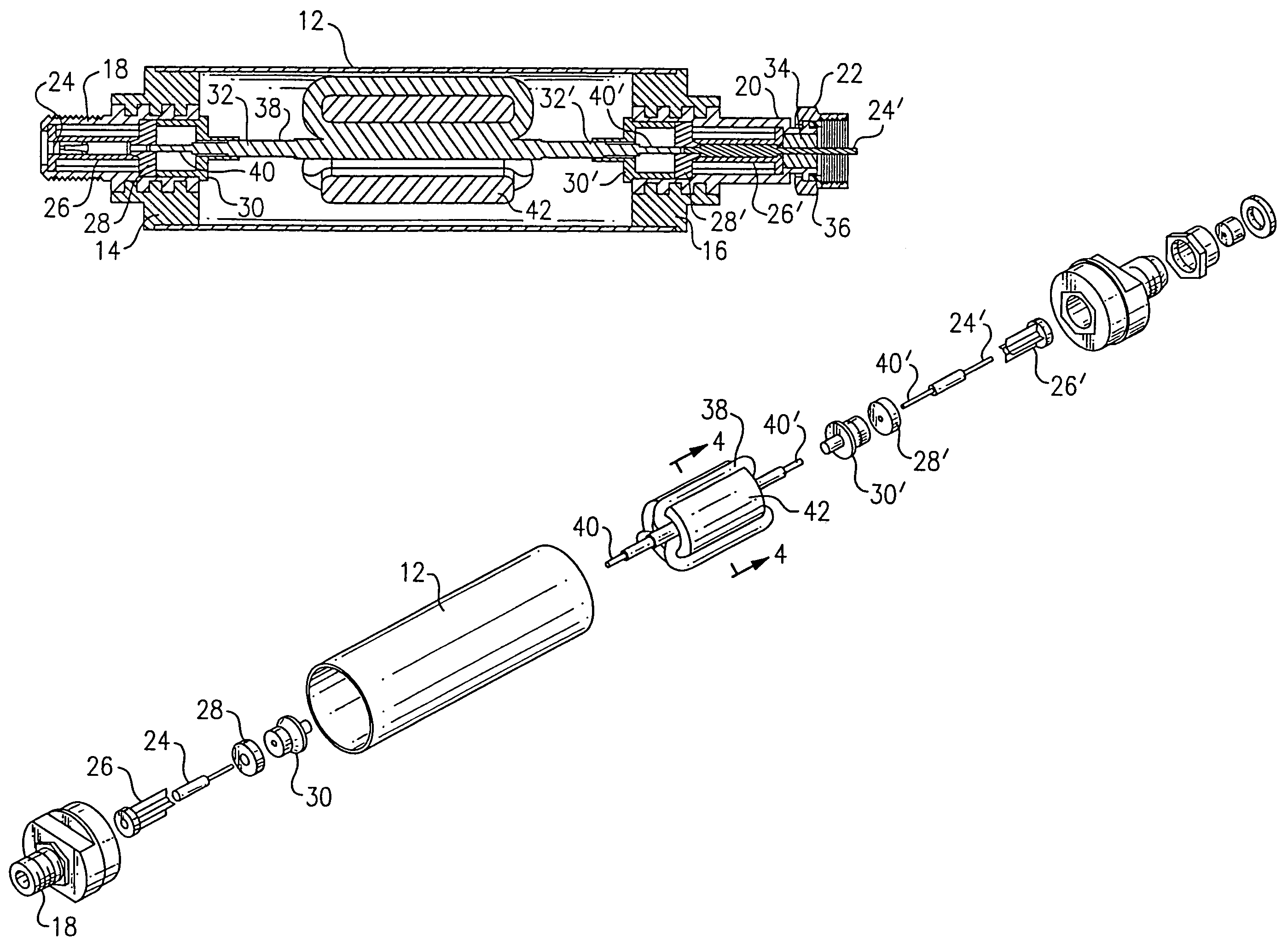
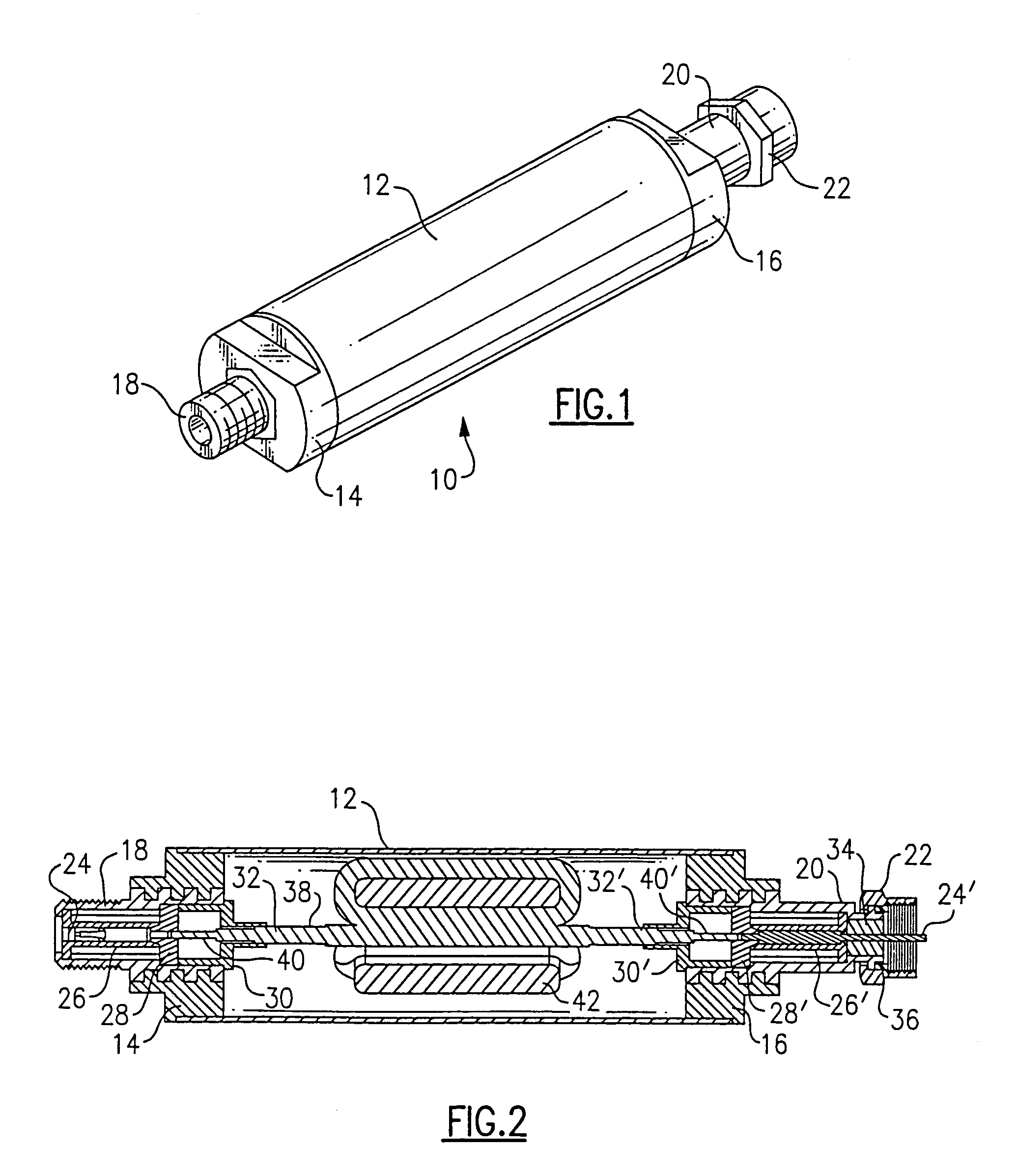
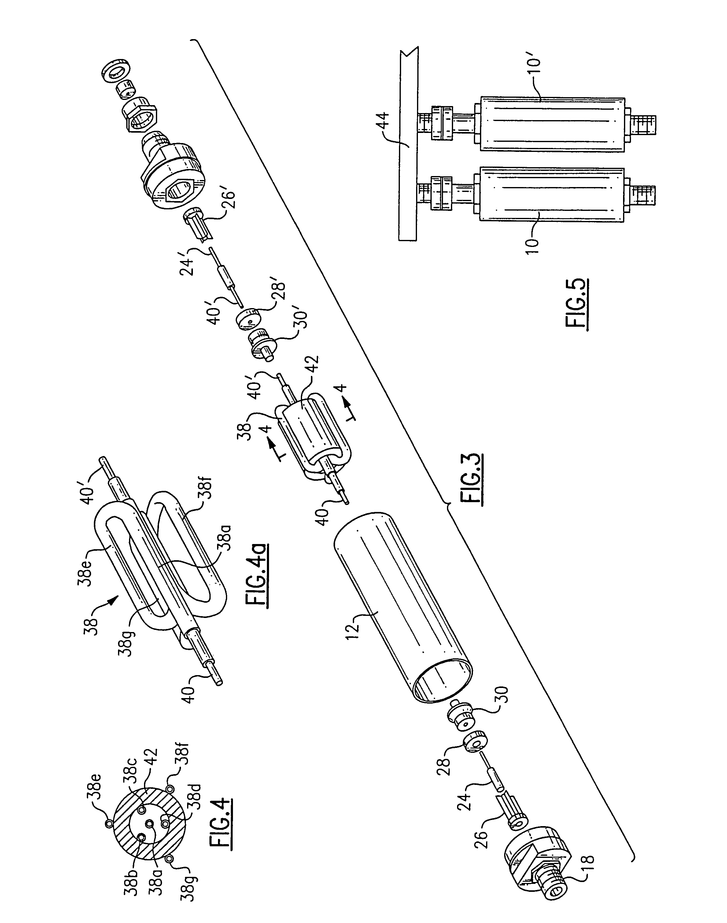
[0030]Referring now to the drawings, in FIG. 1 is shown the preferred embodiment of the device of the invention, denoted generally by reference numeral 10, in fully assembled condition. Device 10 includes cylindrical housing 12, end caps 14 and 16, female connector body 18, and male connector body 20, and nut 22 threadedly engaged on the end of male connector body 20. Elements positioned internally of the housing, end caps and connector bodies, as seen in FIGS. 2 and 3, are female contact 24, contact insulator 26, retaining washer 28, and solder body 30 with solder joint 32 at the female end. Corresponding parts at the male end are male contact 24′, contact insulator 26′, retaining washer 28′, and solder body 30′ with solder joint 32′, in addition to front insulator 34 and gasket 36. Preferred materials for these elements are: ABS plastic for housing 12 and end caps 14, 16; brass alloy with tin plated finish for female and male connector bodies 18 and 20, respectively, nut 22, femal...


PUM


Abstract

A device for use with coaxial cable to attenuate sheath currents associated therewith. The device is adapted to be coupled to incoming and outgoing coaxial cables and includes a ferrite core configured as a first hollow cylinder mounted coaxially within a housing configured as a second hollow cylinder. A conductor within the housing has opposite ends positioned for electrical contact with the incoming and outgoing coaxial cables and an intermediate portion passing through the ferrite core longitudinally at least twice, being passed back over the outside surface of the core between passes therethrough. The elements are so dimensioned that the outside diameter of the housing is less than one inch, thereby allowing side-by-side mounting of a plurality of the devices on industry-standard, multi-port taps which have center-to-center spacings of one inch.

Description

FIELD OF THE INVENTION[0001]The present invention relates to devices for use with cable TV coaxial cables, and more specifically to devices configured and dimensioned for installation on conventional multi-port taps for attenuating so-called sheath current associated with the outer surface of the coaxial cable outer conductor.BACKGROUND OF THE INVENTION[0002]Studies of broadband coaxial cable distribution plants have shown that secondary, “off-air” RF signals picked up by (or impressed upon) the cable system coaxial cable are carried by the cable shielding as a current, commonly termed a sheath current. This current can result in ingress and egress problems due to openings in the cable outer conductor and / or poor connector attachment, as well as “ghosting” of the displayed image. Also, sheath currents propagate from the outer conductor to the ground soil and / or ground block and can accelerate galvanic corrosion within the cable outer conductor.[0003]Efforts to address the problems a...

Claims


Application Information

Patent Timeline
Patent Type & Authority Patents(United States)
IPC IPC(8): H01R11/30H01R13/60H01R9/05H01R13/646
CPCH01R24/42H01R24/542H01R2103/00
Inventor PIXLEY, HENRYPALINKAS, RAYMONDBENSON, ROBERT
Owner PPC BROADBAND INC
Why Eureka
Try Eureka