Bi-directional LED-based light

a led-based light and led-based technology, applied in the field of light, can solve the problems of frequent replacement of dc devices, inconvenient maintenance of led-based lights, and inefficient energy use of incandescent bulbs,

Active Publication Date: 2006-05-30
NG WINNIE LAI LING
View PDF6 Cites 81 Cited by
  • Summary
  • Abstract
  • Description
  • Claims
  • Application Information

AI Technical Summary

Benefits of technology

[0012]A lighting arrangement comprises a source of electrical power and at least one pair of light-emitting diodes (LEDs) driven by the power source. The power source may have different characteristics. Advantageously, the power source supplies unrectified alternating current to each LED pair, although various embodiments of the invention provide advantages even in applications whose power source supplies direct current.

Problems solved by technology

However, incandescent bulbs, and to a lesser extent even plasma-based fluorescent and halogen lights, are generally inefficient in terms of energy use and are subject to frequent replacement due to their limited lifetime.
Being diodes, one problem with LEDs is that they are direct-current (DC) devices that are easily damaged by too high reverse voltage, whereas the power supplies for many devices that would benefit from the advantages of LEDs deliver alternating current (AC).
One drawback of this approach is that four rectifying diodes are typically needed and each of these rectifying diodes must carry half the full current load of all the LEDs.
This is a much simpler circuit than is needed for full-wave rectification, but even it has at least three major drawbacks: First, the light emitted from the LEDs will flicker, for example, at 120 Hz in case the AC power source frequency is 60 Hz.
Failure to do so can lead to a cascade failure of the LEDs; this failure is most prominent in transient conditions.
Third, the rectifying diode must carry the full current load of the LEDs.
It would be possible to mount LED units within the casings—usually bulbs—of the original lights, but this complicates the manufacture of such LED replacements.
Yet another concern is that incandescent elements can typically be mounted without regard to polarity, whereas existing LED arrangements cannot.
When installing an LED replacement in a DC system such as an automobile tail light, there is therefore a risk of incorrect installation because even with a given fitting, the polarity of the wiring is not always the same from one car manufacturer to another.

Method used


Image

  • Bi-directional LED-based light
  • Bi-directional LED-based light
  • Bi-directional LED-based light

Examples


Embodiment Construction

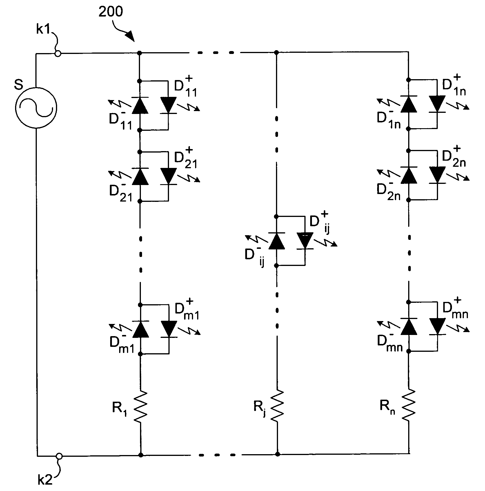
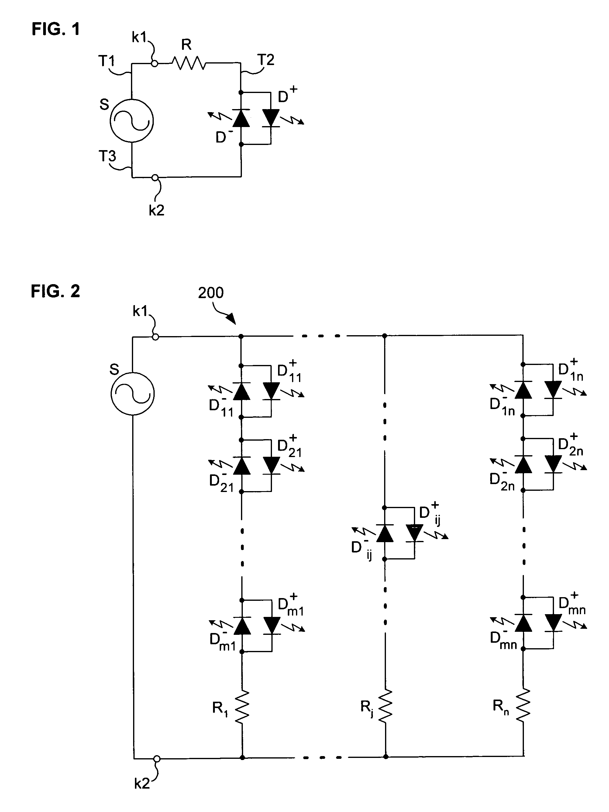
[0037]FIG. 1 is a circuit diagram that illustrates the fundamental embodiment of the invention: A pair of LEDs D+ and D− are connected in parallel, with reverse polarity (with the anode of D+ connected to the cathode D− and the anode of D− connected to the cathode of D+), in series with a current-limiting device, R, typically a resistor, and driven via contacts k1, k2 by a power (or, equivalently, voltage or current) source S that delivers either alternating or direct current.

[0038]In applications that require illumination (such as reading lights) as opposed to simple indication (such as on / off), the LEDs D+ and D− are preferably of the super-luminescent type, for obvious reasons. Even a minimally skillful electrical engineer will be able to choose the actual type of LEDs used, as well as the type and value of the resistor R, to fit the needs of a given application given the specifications of the power source S, in particular, its peak delivered voltage.

[0039]Assume for the sake of ...


PUM


Abstract

At least one pair of LEDs, preferably of the super-luminescent type, are connected in parallel but with reverse polarity in series with at least one resistor and driven by a voltage source, which may deliver unrectified alternating current. An array of m series-connected LED pairs may be included in n parallel paths. The printed circuit board in which the LED pair(s) is mounted is adapted to fit into after-market fittings originally intended to receive incandescent light bulbs. In some embodiments, contacts are formed in the edges of lateral protrusions in the PCB.

Description

BACKGROUND OF THE INVENTION[0001]1. Field of the Invention[0002]This invention relates to lights that use multiple light-emitting diodes, as well as to fixtures for mounting such lights.[0003]2. Description of the Related Art[0004]Incandescent light bulbs are commonly used for indicator lamps, task lamps, general lighting, decorative lamps, warning lamps, traffic lamps and the like. However, incandescent bulbs, and to a lesser extent even plasma-based fluorescent and halogen lights, are generally inefficient in terms of energy use and are subject to frequent replacement due to their limited lifetime. Significant savings can be made by the use light bulbs where the source of light is light-emitting diodes (LED).[0005]LEDs are much more efficient (in terms of lumens per watt) than incandescent and fluorescent lights; moreover, LEDs generally last much longer. This is particularly true of the class of LEDs known as “super-luminescent” or “super-bright,” which have already found uses in...

Claims


Application Information

Patent Timeline
Patent Type & Authority Patents(United States)
IPC IPC(8): H05B41/00H05K
CPCH05B33/0803F21K9/13H05B33/0821F21Y2101/02F21Y2113/005Y10S362/80F21K9/23F21Y2107/90F21Y2113/13F21Y2115/10H01L2224/48247H01L2224/48257H05B45/10H05B45/3574H05B45/42Y02B20/30
Inventor NG, JAMES K.
Owner NG WINNIE LAI LING
Why Eureka
Try Eureka