Tube cleaning machine

a cleaning machine and tube technology, applied in the direction of mechanical equipment, cleaning using liquids, lighting and heating apparatus, etc., can solve the problems of excessive slippage and exceed the rotational speed of the cleaning brush, and achieve the effect of reducing the undesirable slippage of the cleaning brush par

Inactive Publication Date: 2006-06-06
GOODWAY TECH CORP
View PDF6 Cites 22 Cited by
  • Summary
  • Abstract
  • Description
  • Claims
  • Application Information

AI Technical Summary

Benefits of technology

[0009]In accordance with the invention, the operating motor is provided with a potentiometer for controlling motor speed and thereby brush speed as well as pressure and flow of water (and chemical if desired) through a tube. In this way the operator selects the proper brush speed for tube cleaning especially for enhanced tubes to minimize undesirable slip of a cleaning brush part the grooves of an enhanced tube.

Problems solved by technology

Excessive slip will not allow the brush bristles into the grooves thus leaving them fouled.
Excessive slip occurs when rotational speed of the brush exceeds the natural feed rate of the rifling helix in the tube.

Method used


Image

  • Tube cleaning machine
  • Tube cleaning machine
  • Tube cleaning machine

Examples


Embodiment Construction

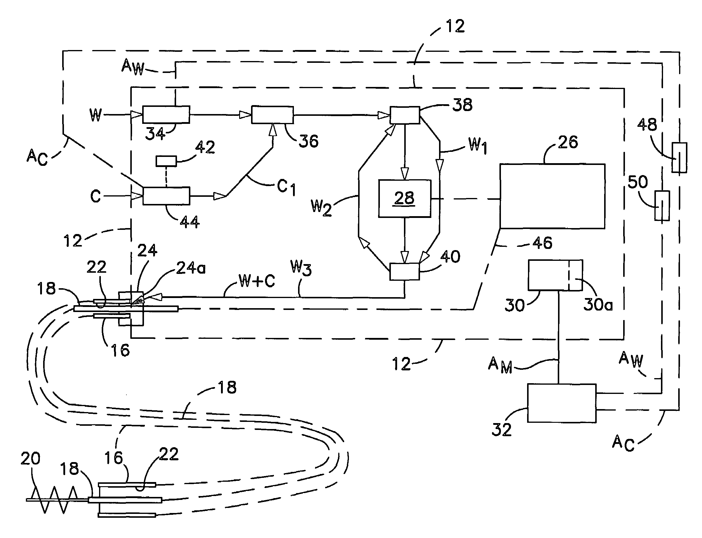
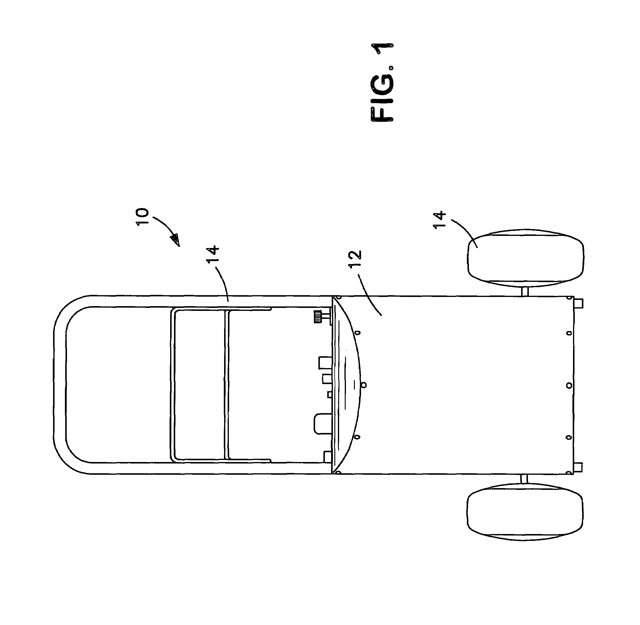
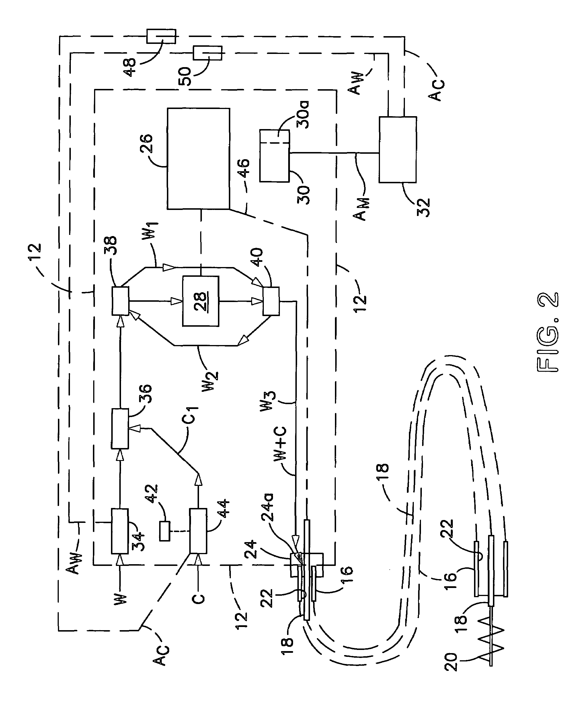
[0013]Referring to FIGS. 1 and 2 of the drawing, the tube cleaning machine 10 includes a power console 12 mounted on a hand truck 14 and an elongate sheath 16 (FIG. 2) which encases a flexible drive shaft 18 for rotating a tube cleaning brush 20 mounted at the far end of the flexible shaft. The sheath defines an enclosed interior channel 22 for passage of water W and cleaning chemicals C from the power console to the brush end of the sheath. An end cap 24 mounts sheath and flexible drive shaft to the power console and has openings 24a for passage of water and chemicals into the sheath interior channel. The operating components of the tube cleaning machine shown in schematic form in FIG. 2 are mounted within the power console.

[0014]Referring to FIG. 2, the operating components of the tube cleaning machine include a electric drive motor 26 for rotating the flexible rotary shaft 18 and for driving a tube cleaning water pump 28. The motor has a motor controller 30 with an air switch act...


PUM


Abstract

A tube cleaning machine for industrial smooth bore tubes and enhanced tubes in which the machine includes a rotary brush with means for selecting brush rotary speed for optimum cleaning of the smooth bore and enhanced tubes, and in which the machine includes a water side and a chemical side for supplying a cleaning medium to tubes being cleaned.

Description

RELATED APPLICATION[0001]This application is directed to the inventions described in U.S. Provisional Application Ser. Nos. 60 / 336,034 and 60 / 336,035, both filed Nov. 15, 2001, and claims priority of said applications.BACKGROUND OF THE INVENTION[0002]The present invention is directed to tube cleaning machines for cleaning the tubes and pipes of power plant equipment such as boilers, condensers, heat exchangers and so forth. In tube cleaning such equipment, an operator uses commercially available equipment such as described in U.S. Pat. Nos. 5,235,718 and 5,426,807. Such equipment comprises a rotating brush and water flush that an operator inserts into each tube to be cleaned. The equipment rotates the brush by means of a drive shaft and propels the brush and sheath encased drive shaft the full length of each tube for cleaning, provides the water flush, and withdraws the brush after the tube is so cleaned.[0003]Tube cleaning brushes have a twisted wire spine securing bristles in a sp...

Claims


Application Information

Patent Timeline
Patent Type & Authority Patents(United States)
IPC IPC(8): B08B9/00
CPCB08B9/045B08B9/0436
Inventor FRANZINO, JOSEPH J
Owner GOODWAY TECH CORP
Why Eureka
Try Eureka