Steerable obturator

a technology of obturator and cannula, which is applied in the field of body implantable leads, can solve the problems of difficult implantation of lead in the coronary sinus region and lack of adequate control, and achieve the effect of facilitating the passage of the distal end section

Inactive Publication Date: 2006-06-06
PACESETTER INC
View PDF18 Cites 103 Cited by
  • Summary
  • Abstract
  • Description
  • Claims
  • Application Information

AI Technical Summary

Benefits of technology

The patent describes a device called an omnidirectionally steerable obturator that helps to deliver a distal tip of an introducer sheath into the coronary sinus of a heart. This device has a flexible, deflectable distal end section that can be controlled by an actuator to move in different directions, making it easier to guide the device into the heart. The technical effect of this device is to improve the accuracy and efficiency of delivering a distal tip of an introducer sheath into the coronary sinus of a heart.

Problems solved by technology

The patent text describes a method for implanting leads in the heart to treat various conditions. The technical problem addressed in the text is the difficulty of accurately locating the coronary sinus ostium and steering the introducer sheath through the coronary sinus to cannulate the coronary sinus. The text describes the use of an introducer sheath and dilator to facilitate the placement of leads in the heart.

Method used


Image

  • Steerable obturator
  • Steerable obturator
  • Steerable obturator

Examples


first embodiment

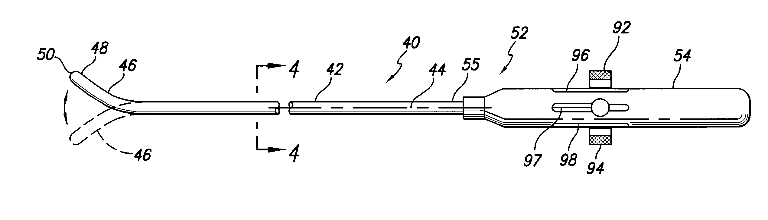
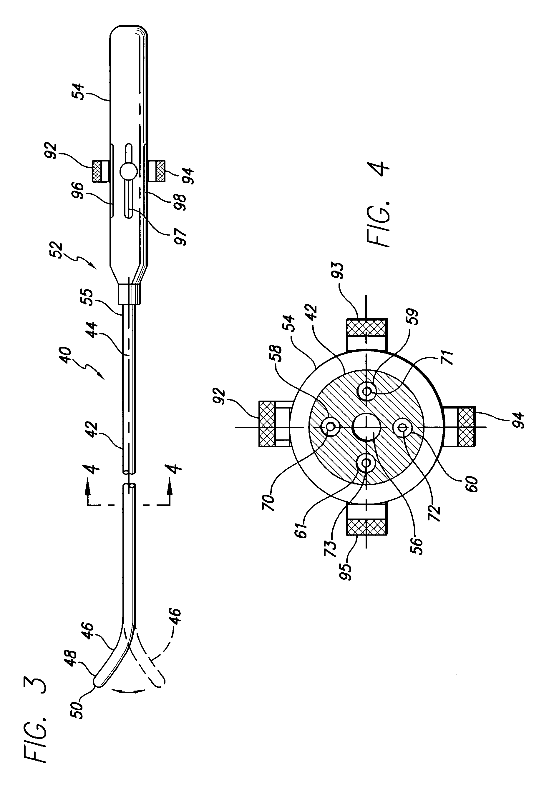
[0038]FIGS. 3–8 show a steerable obturator 40 in accordance with the invention. The obturator 40 comprises an elongated obturator body 42 extending along a longitudinal, central axis 44. The obturator body includes a flexible, omnidirectionally deflectable distal end section 46 terminating at a distal tip 48 having a curved or rounded outer tip surface 50. The distal end section 46 of the obturator body may comprise a short section that is more flexible than the remainder of the obturator body. A directional actuator 52 is provided for deflecting the flexible distal end section 46. In accordance with one embodiment of the invention, the actuator 52 includes a control handle 54 attached to a proximal end 55 of the obturator body 42.

[0039]The obturator body 42 comprises a generally tubular structure fabricated of any suitable biostable, biocompatible, flexible material, for example, a braided stainless steel wire embedded in a thermoplastic resin such as that sold under PEBAX®, a trad...

second embodiment

[0053]FIG. 17 shows a specific, exemplary form of an obturator 150 in accordance with another embodiment of the invention which eliminates the need for actuating members in the form of wires or cables and related elements. The obturator 150 includes an obturator body 152 having a flexible, distal end section 154 terminating at a tip 156 having an outer rounded surface 158. A handle 160 is attached to the proximal end of the obturator body 152. The obturator includes a central, longitudinal lumen 162 extending the length of the obturator for receiving an actuator 164 for deflecting the flexible distal end section 154. With reference to FIG. 18, the actuator 164 of the second embodiment is in the form of a stylet 166 having a pre-curved distal end 168, for example, in the form of a J-shape, and a proximal end carrying a torque knob 170. When the stylet 166 is fully inserted in the obturator 150 as shown in FIG. 19, the pre-curved distal end 168 deflects the flexible distal end section...


PUM


Abstract

An omnidirectionally steerable obturator facilitates the delivery of the distal tip of an introducer sheath into the coronary sinus of a heart. The steerable obturator comprises an obturator body extending longitudinally along a central axis, the obturator body being configured to be received by the introducer sheath. The obturator body further has a flexible, deflectable distal end section terminating in a rounded distal tip. An actuator, controllable from a proximal end of the obturator body, is operatively associated with the flexible distal end section of the obturator body to cause deflection of the flexible distal end section of the obturator body in at least one selected direction to facilitate passage of the distal end section of the obturator body and the distal tip of the introducer sheath into the coronary sinus of the heart.
The obturator body is preferably configured to be received in a close fit within at least the tip of the introducer sheath. More preferably, the distal end of the obturator body has an outer surface and the fit between the outer surface of the obturator and at least the tip of the introducer sheath comprises substantially a line-to-line fit.

Description


Claims


Application Information

Patent Timeline
Owner PACESETTER INC
Why Eureka
Try Eureka