Position measuring device

a technology of positioning and measuring device, which is applied in the direction of measuring device, optical conversion of sensor output, instruments, etc., can solve the problems of detection of wrong position of scanning device, difficult to distinguish, and difficult to d

Inactive Publication Date: 2006-06-06
DR JOHANNES HEIDENHAIN GMBH
View PDF16 Cites 4 Cited by
  • Summary
  • Abstract
  • Description
  • Claims
  • Application Information

AI Technical Summary

Benefits of technology

[0010]It is therefore an object of the present invention to disclose a position measuring device by which it is possible to more assuredly differentiate between several measuring areas next to the reference markings.
[0012]The position measuring device designed in accordance with the present invention has the particular advantage that the assurance of an unequivocal differentiation as to whether the scanning device is located on one or the other side of the reference markings is relatively great. The safeguard against interference is increased.

Problems solved by technology

It has been shown that because of the signal levels of this measuring signal this differentiation is problematic, since the mutual distance between the levels is very short.
This measuring signal can also easily be affected by partial soiling or contamination of the scale, so that a wrong position of the scanning device is detected.

Method used


Image

  • Position measuring device
  • Position measuring device
  • Position measuring device

Examples


Embodiment Construction

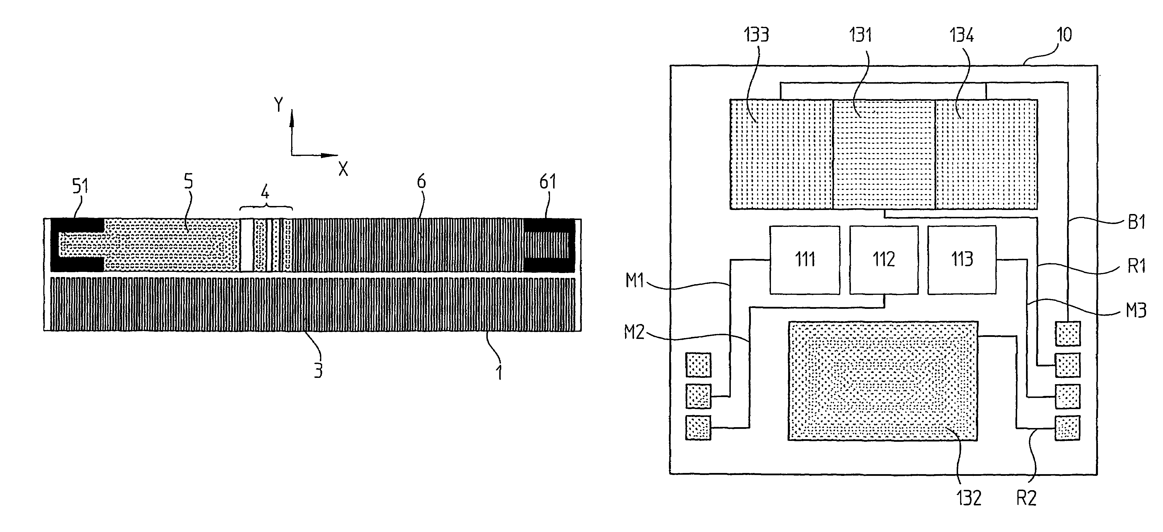
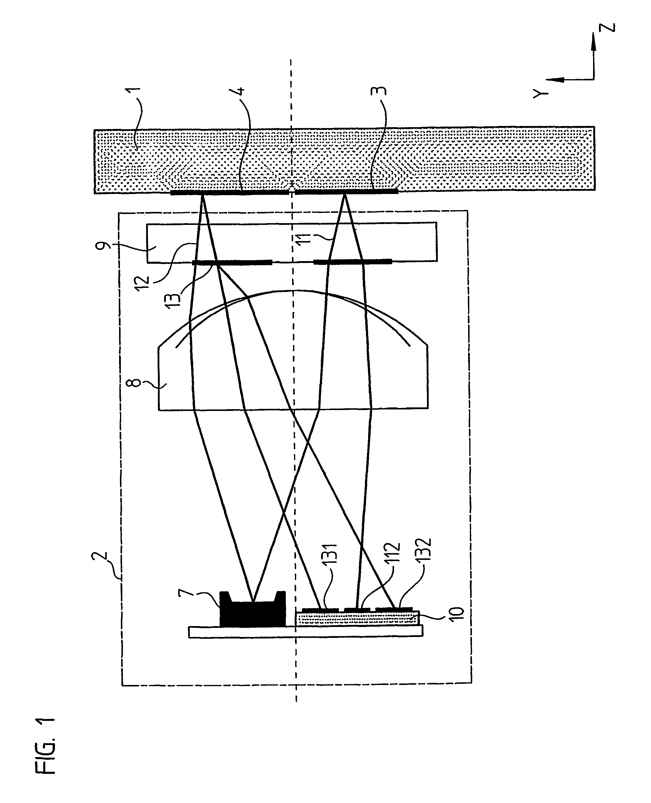
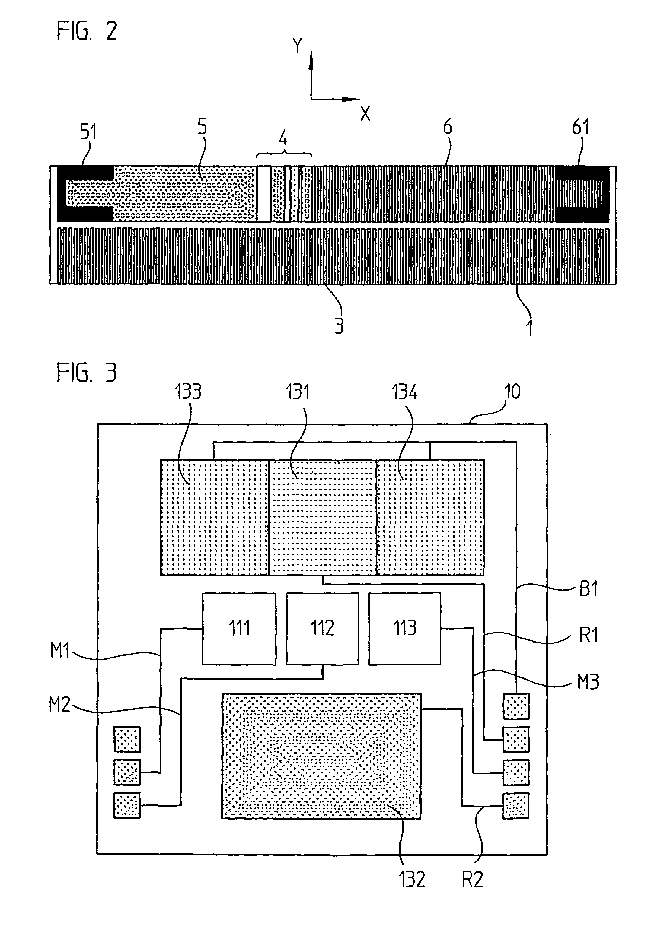
[0026]A photoelectric incremental position measuring device in the form of a linear measuring device, having a scale 1, which can be displaced in the measuring direction X in relation to a scanning device 2, is shown in FIG. 1. A periodic incremental measuring graduation 3 has been applied to the scale 1 in a first track, and in a second track a reference marking 4, as well as area markings 5 and 6. For photoelectric scanning of the scale 1, the scanning device 2 includes a light source 7, whose light is bundled in a collimator 8 and is directed through a scanning plate 9 onto the scale 1. The light impinging on the scale 1 is reflected in a position-dependent manner at the measuring graduation 3, the reference marking 4, as well as the area markings 5 and 6 and impinges on the photo receiver arrangement 10. The scale 1 is represented in a view from above in FIG. 2, and the photo receiver arrangement 10 in FIG. 3. How the light is affected as a function of position is represented in...


PUM


Abstract

A position measuring device having a scanning device and a scale, wherein the scanning device is movable in relation to the scale in a measuring direction. The scale including a measuring graduation, wherein periodic measuring signals are generated when the scanning device scans the measuring graduation and a reference marking, wherein a reference marking signal is generated when the scanning device scans the reference marking with a scanning beam bundle. The scale further includes a first optically scannable area marking next to the reference marking and a second optically scannable area marking next to the reference marking and which has a different optical deflection property than the first optically scannable area marking, wherein photoelectric scanning of the first and second optically scannable area markings with the scanning beam bundle from the scanning device generates an area signal that differentiates characteristics of the first and second optically scannable area markings. A first photo-receiver receives light from the first optically scannable area marking and a second photo-receiver receives light from the second optically scannable area marking.

Description

[0001]Applicants claim, under 35 U.S.C. §§ 120 and 365, the benefit of priority of the filing date of Jul. 5, 2002 of a Patent Cooperation Treaty patent application, copy attached, Serial Number PCT / EP02 / 07453, filed on the aforementioned date, the entire contents of which are incorporated herein by reference, wherein Patent Cooperation Treaty patent application Serial Number PCT / EP02 / 07453 was not published under PCT Article 21(2) in English.[0002]Applicants claim, under 35 U.S.C. § 119, the benefit of priority of the filing date of Jul. 9, 2001 of a German patent application, copy attached, Serial Number 101 32 521.5, filed on the aforementioned date, the entire contents of each of which are incorporated herein by reference.BACKGROUND OF THE INVENTION[0003]1. Field of the Invention[0004]The present invention relates to a position measuring device.[0005]2. Description of the Related Art[0006]Such position measuring devices are employed in particular in connection with processing ma...

Claims


Application Information

Patent Timeline
Patent Type & Authority Patents(United States)
IPC IPC(8): G01D5/34G01B11/00G01D5/245G01D5/36G01D5/38
CPCG01D5/2457G01D5/38G01D5/366
Inventor GRUBER, ALEXANDERHERMANN, MICHAELHOLZAPFEL, WOLFGANGKUHLER, MARKUSPRONOLD, HERBERTTONDORF, SEBASTIAN
Owner DR JOHANNES HEIDENHAIN GMBH
Why Eureka
Try Eureka