Method and apparatus for achieving physical connection between the flux guide and the free layer and that insulates the flux guide from the shields

a flux guide and free layer technology, applied in the field of magnetoresistive (mr) heads, to achieve the effect of enhancing output signal, increasing magnetic flux, and increasing the amount of magnetic flux

Inactive Publication Date: 2006-06-06
HITACHI GLOBAL STORAGE TECH NETHERLANDS BV
View PDF24 Cites 17 Cited by
  • Summary
  • Abstract
  • Description
  • Claims
  • Application Information

AI Technical Summary

Benefits of technology

[0014]A method in accordance with the principles of the present invention includes forming a tunnel valve at a first shield layer, the tunnel valve comprising a free layer distal to the first shield layer, depositing a first insulation layer over the first shield layer and around the tunnel valve, depositing a flux guide over the first insulation layer and coupling to the tunnel valve at the free layer, covering the flux guide with a second insulation layer and forming a second shield layer over the second insulation, wherein the flux guide and the free layer are physically isolated by the first and second insulation layers to prevent current shunts therefrom.
[0029]Another aspect of the present invention is that the increase in the amount of magnetic flux in the tunnel valve enhances the output signal fo the tunnel valve.

Problems solved by technology

However, when the disk rotates, air is swirled by the rotating disk adjacent the ABS causing the slider to ride on an air bearing a slight distance from the surface of the rotating disk.
In addition, many antiferromagnets used to fix the magnetic moment of the fixed ferromagnetic layer contain manganese (Mn) which can corrode during the ABS lapping process.
The tunnel barrier layer is typically formed of aluminum oxide, which can also corrode during the ABS lapping process.

Method used


Image

  • Method and apparatus for achieving physical connection between the flux guide and the free layer and that insulates the flux guide from the shields
  • Method and apparatus for achieving physical connection between the flux guide and the free layer and that insulates the flux guide from the shields
  • Method and apparatus for achieving physical connection between the flux guide and the free layer and that insulates the flux guide from the shields

Examples


Embodiment Construction

[0041]In the following description of the exemplary embodiment, reference is made to the accompanying drawings which form a part hereof, and in which is shown by way of illustration the specific embodiment in which the invention may be practiced. It is to be understood that other embodiments may be utilized as structural changes may be made without departing from the scope of the present invention.

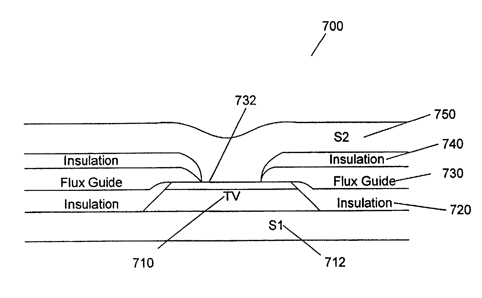
[0042]The present invention provides a method and apparatus for providing a structure that achieves physical connection between the flux guide and the free layer and that insulates the flux guide from the shields. By separating the flux guide and the free layer from the shields, the shunting of current is prevented.

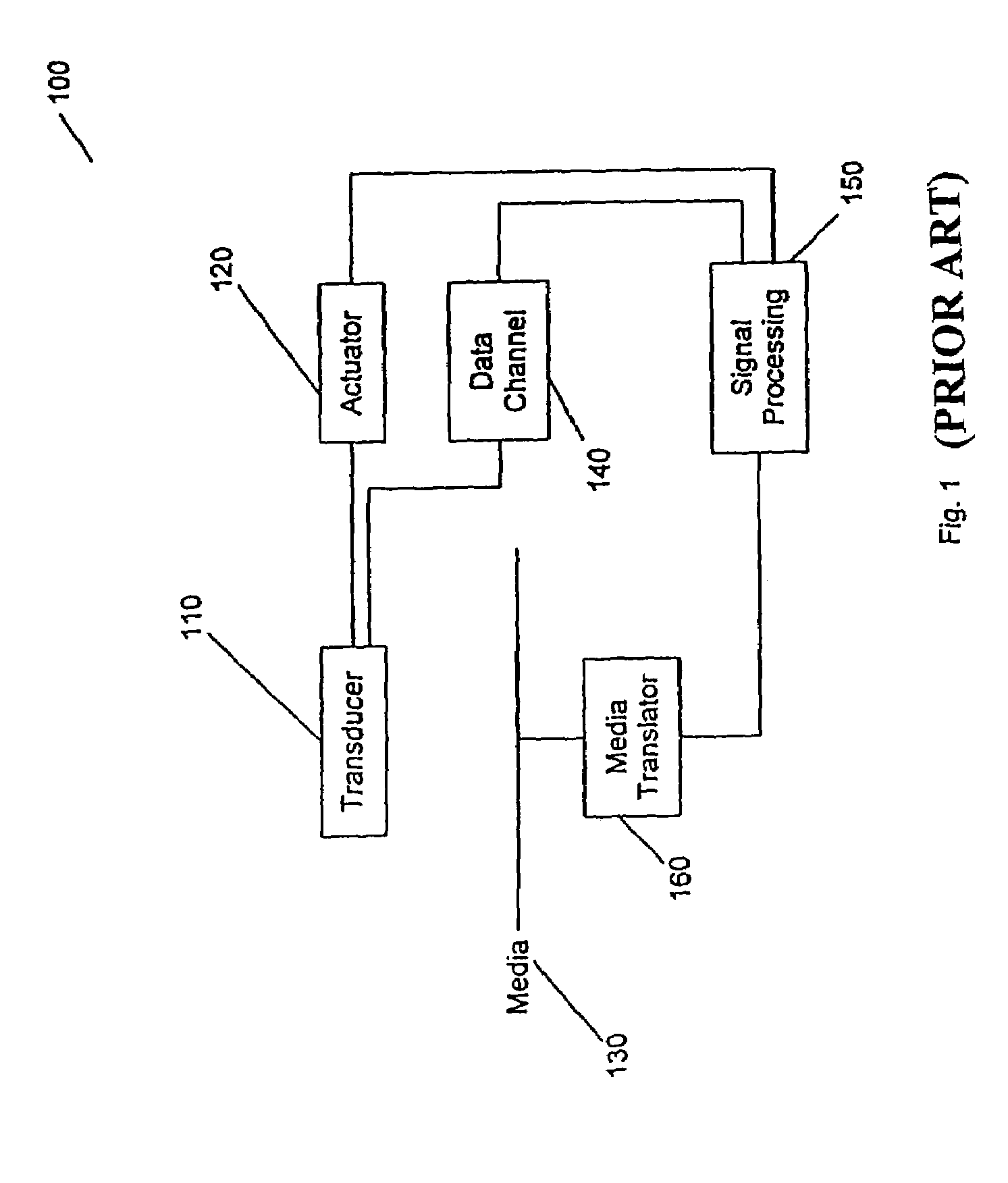
[0043]FIG. 1 illustrates a storage system 100 according to the present invention. In FIG. 1, a transducer 110 is under control of an actuator 120. The actuator 120 controls the position of the transducer 110. The transducer 110 writes and reads data on magnetic media 130. The re...


PUM

PropertyMeasurementUnit
magnetic fluxaaaaaaaaaa
antiferromagneticaaaaaaaaaa
AFMaaaaaaaaaa

Abstract

A method for making a tunnel valve head with a flux guide, a tunnel valve sensor having an isolated flux guide, and a magnetic storage system using a tunnel valve sensor having an isolated flux guide is disclosed. The tunnel valve sensors is created by forming a tunnel valve at a first shield layer, the tunnel valve comprising a free layer distal to the first shield layer, depositing a first insulation layer over the first shield layer and around the tunnel valve, depositing a flux guide over the first insulation layer and coupling to the tunnel valve at the free layer, covering the flux guide with a second insulation layer and forming a second shield layer over the second insulation, wherein the flux guide and the free layer are physically isolated by the first and second insulation layers to prevent current shunts therefrom. The structure achieves physical connection between the flux guide and the free layer and insulates the flux guide from the shields. By separating the flux guide and the free layer from the shields, the shunting of current is prevented.

Description

BACKGROUND OF THE INVENTION[0001]1. Field of the Invention[0002]This invention relates in general to magnetoresistive (MR)heads for reading magnetically recorded data, and more particularly to a method and apparatus for providing a structure that achieves physical connection between the flux guide and the free layer and that insulates the flux guide from the shields.[0003]2. Description of Related Art[0004]Magnetic recording is a key and invaluable segment of the information-processing industry. While the basic principles are one hundred years old for early tape devices, and over forty years old for magnetic hard disk drives, an influx of technical innovations continues to extend the storage capacity and performance of magnetic recording products. For hard disk drives, the areal density or density of written data bits on the magnetic medium has increased by a factor of more than two million since the first disk drive was applied to data storage. Since 1991, areal density has grown b...

Claims


Application Information

Patent Timeline
Patent Type & Authority Patents(United States)
IPC IPC(8): G11B5/39G11B5/40
CPCB82Y10/00B82Y25/00G11B5/3903G11B5/3909G11B5/3916G11B5/40Y10T29/49055Y10T29/49052Y10T29/49048Y10T29/49044Y10T29/49046Y10T29/49043G11B2005/3996
Inventor GILL, HARDAYAL SINGH
Owner HITACHI GLOBAL STORAGE TECH NETHERLANDS BV
Why Eureka
Try Eureka