MEMS micro-lens driven by three piezoelectric cantilever beams and manufacturing method thereof

A cantilever beam and piezoelectric technology, applied in the direction of microstructure technology, microstructure devices, manufacturing microstructure devices, etc., can solve the problems of difficult to meet the multi-axis deflection direction of the micromirror, weak piezoelectric performance, small driving force, etc., to achieve The effect of multiple deflection directions, low working voltage and large driving force

Inactive Publication Date: 2011-01-05
BEIJING INSTITUTE OF TECHNOLOGYGY
View PDF4 Cites 16 Cited by
  • Summary
  • Abstract
  • Description
  • Claims
  • Application Information

AI Technical Summary

Problems solved by technology

[0007] The purpose of the present invention is to solve the problem that the traditional MEMS micromirror structure is difficult to meet the requirements of the micromirror on the multi-axis deflection direction in terms of optical opening, optical scanning and optical imaging, etc., and to select a PZT film with a thickness of less than 2 μm as the driving material, resulting in piezoelectric performance. Weak, small driving force and other shortcomings, and provide a MEMS micromirror driven by a three-piezoelectric cantilever beam and its manufacturing method

Method used


Image

  • MEMS micro-lens driven by three piezoelectric cantilever beams and manufacturing method thereof
  • MEMS micro-lens driven by three piezoelectric cantilever beams and manufacturing method thereof
  • MEMS micro-lens driven by three piezoelectric cantilever beams and manufacturing method thereof

Examples


Embodiment

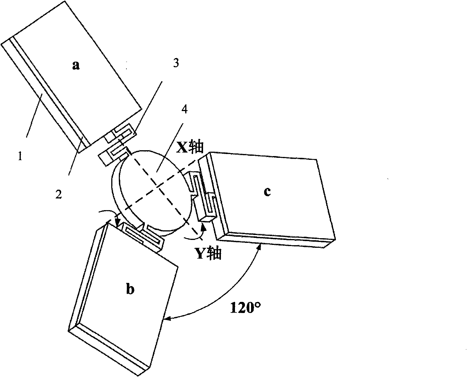
[0029] Such as figure 1 Shown, a kind of MEMS micromirror driven by three piezoelectric cantilever beams of the present invention comprises a microreflector 4, three piezoelectric cantilever beams and three arcuate curved elastic narrow beams 3, and the piezoelectric cantilever beams are made of silicon cantilever beams 1 Composed of a PZT drive film 2 with a fixed surface thickness of 3 μm; three piezoelectric cantilever beams are respectively connected to the micro-mirror surface 4 through three bow-shaped curved elastic narrow beams 3, and the three piezoelectric cantilever beams and the micro-mirror surface 4 are all on the same plane Inside, and the piezoelectric cantilever beams are distributed at an angle of 120° between each other.

[0030] The specific production steps are as follows:

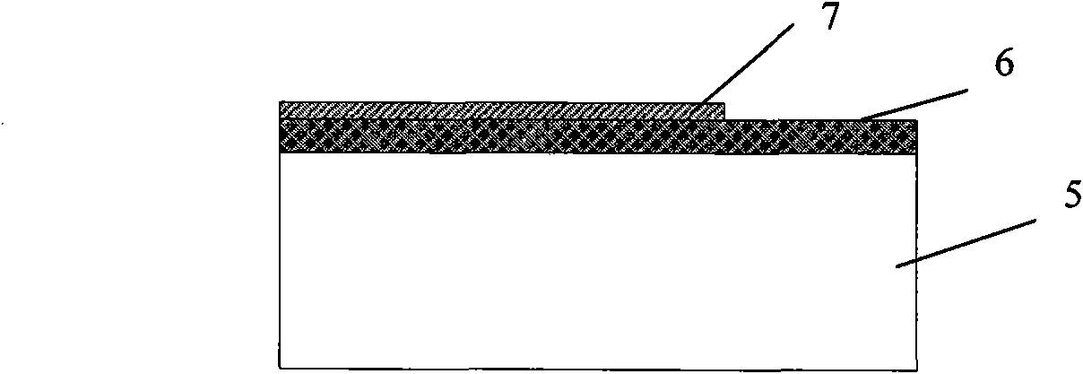
[0031] (1) if figure 2As shown, first, 2 μm SiO was deposited on a single side of a double-polished Si wafer substrate 5 by a physical enhanced chemical vapor deposition (PECVD) pro...


PUM

PropertyMeasurementUnit
thicknessaaaaaaaaaa
thicknessaaaaaaaaaa
thicknessaaaaaaaaaa

Abstract

The invention relates to an MEMS micro-lens driven by three piezoelectric cantilever beams and a manufacturing method thereof and belongs to the technical field of piezoelectric MEMS appliance designs and integrated manufacturing. The MEMS micro-lens comprises a micro-reflecting mirror surface, the piezoelectric cantilever beams and arched bent elastic narrow beams, wherein each of the piezoelectric cantilever beams is formed by fixing a PZT driving membrane with more than 2 mu m thickness on the surface of a silicon cantilever beam; the three piezoelectric cantilever beams are connected with the micro-lens micro-reflecting mirror surface through three arched bent elastic narrow beams respectively; and the piezoelectric cantilever beams are distributed in a way that an included angle of 120 degrees is formed between every two piezoelectric cantilever beams. The manufacturing method comprises the following steps of: firstly, preparing a piezoelectric thick membrane on a substrate and etching piezoelectric cantilever beam patterns on the piezoelectric thick membrane; secondly, preparing a Au / Cr two-layer metal top electrode and a micro micro-reflecting mirror surface pattern on the PZT piezoelectric thick membrane; and finally, etching a Si substrate on the front and back faces so as to form the MEMS micro-lens driven by the three piezoelectric cantilever beams. The MEMS micro-lens has the advantages of many deflecting directions, strong driving force of the PZT thick membrane and low optical loss. The manufacturing process is compatible with the MEMS process, so that the MEMS micro-lens has the potential of mass production and can be widely applied in the field of optical communication.

Description

technical field [0001] The invention relates to a MEMS (micro-electro-mechanical system) micromirror driven by a triple piezoelectric cantilever beam and a manufacturing method thereof, belonging to the technical field of intelligent materials and structures. Background technique [0002] MEMS micromirror is a kind of micro optical modulation device. Its basic principle is to make the movable micromirror surface rotate or translate through the action of static electricity (or magnetic force or electrothermal or piezoelectric), thereby changing the propagation direction or phase of the input light. . MEMS micromirrors and their arrays can be widely used in optical communication and optical signal modulation, optical storage and optical projection imaging, spectral analysis and biomedical instruments, Wavefront correction in astronomy and vision science. [0003] According to the driving mode, MEMS micromirrors can be mainly divided into four types: electrostatic type, magne...

Claims


Application Information

Patent Timeline
Patent Type & Authority Applications(China)
IPC IPC(8): G02B26/08B81C1/00
Inventor 曹茂盛赵全亮袁杰
Owner BEIJING INSTITUTE OF TECHNOLOGYGY
Why Eureka
Try Eureka