Method and system for reducing longitudinal fluid flow around a permeable well

a permeable well and fluid flow technology, applied in drinking water installation, borehole/well accessories, constructions, etc., can solve the problems of limited production campaigns, presence or creation of considerable annular space, etc., and achieve economic and effective effects

Inactive Publication Date: 2006-06-13
SHELL OIL CO
View PDF12 Cites 105 Cited by
  • Summary
  • Abstract
  • Description
  • Claims
  • Application Information

AI Technical Summary

Benefits of technology

[0007]The present invention aims to solve the problem of longitudinal annular flow around permeable well tubulars in an economical and effective manner.

Problems solved by technology

However, around these permeable tubulars an annular space of a considerable length may be present or created during production as a result of erosion.
Logging procedures which employ downhole spinners that are rotated by the fluid flux inside the tubular will not detect the addition fluid flux through the annulus and may therefore create an Impression that the influx in some regions of the well is smaller than it is in reality.
Ultimately this has led to limited production campaigns.
A disadvantage of the known methods is that they require downhole manipulation of well equipment which is a complex and time consuming procedure that is not suitable for installation of a series of seals at short intervals along the length of an inflow region of a well.

Method used


Image

  • Method and system for reducing longitudinal fluid flow around a permeable well
  • Method and system for reducing longitudinal fluid flow around a permeable well
  • Method and system for reducing longitudinal fluid flow around a permeable well

Examples


Embodiment Construction

[0013]The method according to the invention comprises:

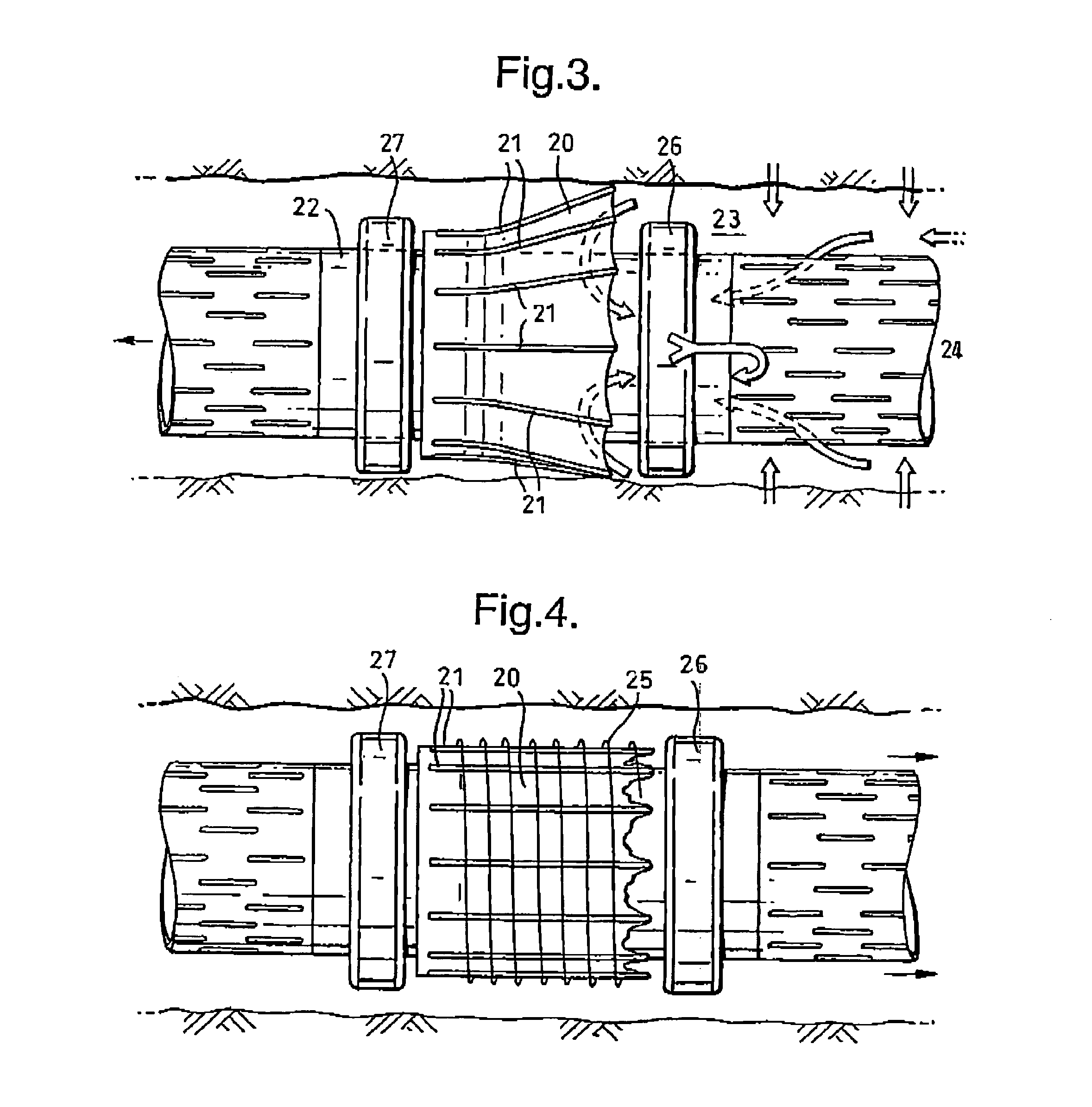
[0014]arranging at least one resilient sealing ring around the permeable tubular before lowering the tubular into the well;

[0015]constraining the ring in a collapsed position around the tubular by means of a tape and / or binder which gradually dissolves in a downhole environment;

[0016]placing the tubular in the inflow region of the well; and

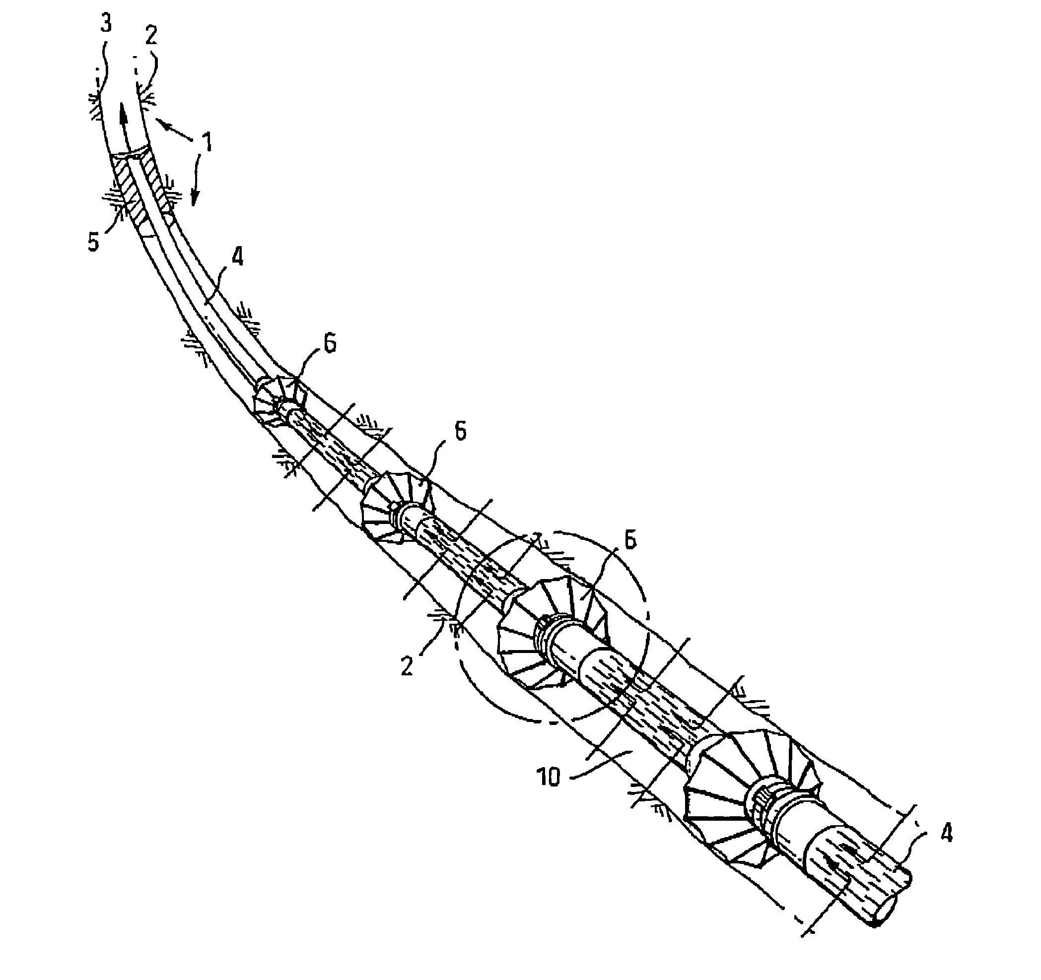
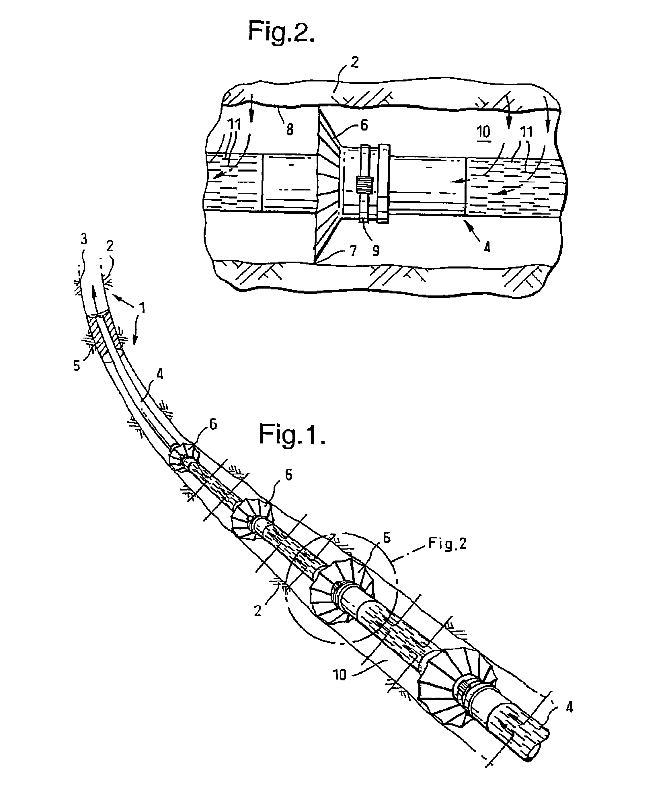
[0017]allowing the tape and / or binder to dissolve thereby allowing at least part of the resilient sealing ring to expand radially in the annular space surrounding the permeable tubular.

[0018]Preferably a series of resilient sealing rings are arranged at regular longitudinal intervals along the length of the permeable tubular and each sealing ring has one end which is permanently clamped to the permeable tubular and a resilient lip-shaped other end which is temporarily clamped around the tubular during installation of the tubular in the well and which is released after installation such that the...


PUM


Abstract

A method for reducing longitudinal flow of fluids through an annular space surrounding a permeable well tubular, such as a slotted liner or a sandscreen, in an inflow region of an oil and/or gas production well having: arranging a series of collapsed resilient sealing rings at regular longitudinal intervals around the permeable tubular before lowering the tubular into the well by means of tape and/or a binder which dissolves downhole; placing the tubular in the inflow region of the well; and allowing the tape and/or binder to dissolve, thereby allowing the resilient sealing rings to expand radially in the annular space surrounding the permeable tubular.

Description

FIELD OF THE INVENTION[0001]The invention relates to a method and system for reducing longitudinal flow of fluids through an annular space surrounding a permeable well tubular, such as a slotted liner or a sandscreen, in an inflow region of an oil and / or gas production well.BACKGROUND OF THE INVENTION[0002]Modern wells have inflow regions which may have a length up to ten kilometers. In these inflow regions elongate permeable tubulars such as slotted liners, expandable slotted tubulars and / or sandscreens may be arranged which preserve the integrity of the borehole and prevent influx of solids and erosion of the borehole wall during production of oil and / or gas.[0003]However, around these permeable tubulars an annular space of a considerable length may be present or created during production as a result of erosion. This erosion may increase as the eroded annulus may increase in length and width and as a result in some wells the fluid flow through the annulus is equal to or even large...

Claims


Application Information

Patent Timeline
Patent Type & Authority Patents(United States)
IPC IPC(8): E21B33/124E21B33/12E21B33/126E21B33/136E21B43/08
CPCE21B33/126E21B43/08E21B33/136
Inventor BOUSCHE, OLAF JEAN PAULRUNIA, DOUWE JOHANNES
Owner SHELL OIL CO
Why Eureka
Try Eureka