Vertebrae fastener placement guide

a technology of fastener and vertical shaft, applied in bone drill guides, medical science, surgery, etc., can solve the problems of inability to use hands in tight operating spa

Inactive Publication Date: 2006-06-13
WARSAW ORTHOPEDIC INC
View PDF41 Cites 178 Cited by
  • Summary
  • Abstract
  • Description
  • Claims
  • Application Information

AI Technical Summary

Problems solved by technology

During the procedure, there always exists a danger of injuring the spinal column by not aiming the drill and screw correctly.
The procedure is further complicated by the tight operating space.
Only a limited number of hands can have access to the tight operating space.
Complications, such as spinal damage, can also ensue if a screw with an improper length is used to fix the adjacent vertebrae together.

Method used


Image

  • Vertebrae fastener placement guide
  • Vertebrae fastener placement guide
  • Vertebrae fastener placement guide

Examples


Embodiment Construction

[0044]For the purposes of promoting an understanding of the principles of the invention, reference will now be made to the embodiments illustrated in the drawings and specific language will be used to describe the same. It will nevertheless be understood that no limitation of the scope of the invention is thereby intended. Any alterations and further modifications in the described embodiments, and any further applications of the principles of the invention as described herein are contemplated as would normally occur to one skilled in the art to which the invention relates. One embodiment of the invention is shown in great detail, although it will be apparent to those skilled in the art that some of the features which are not relevant to the invention may not be shown for the sake of clarity.

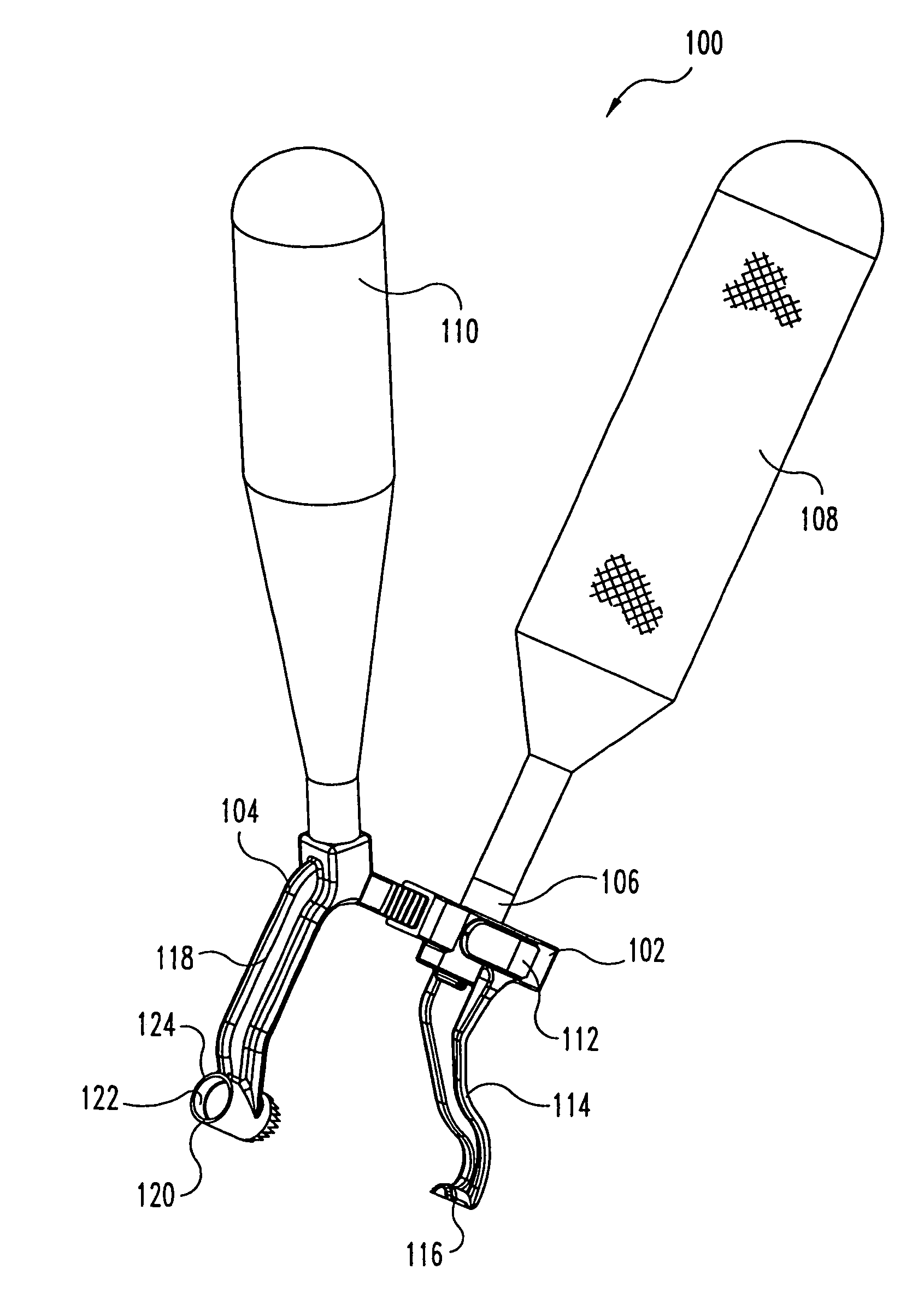
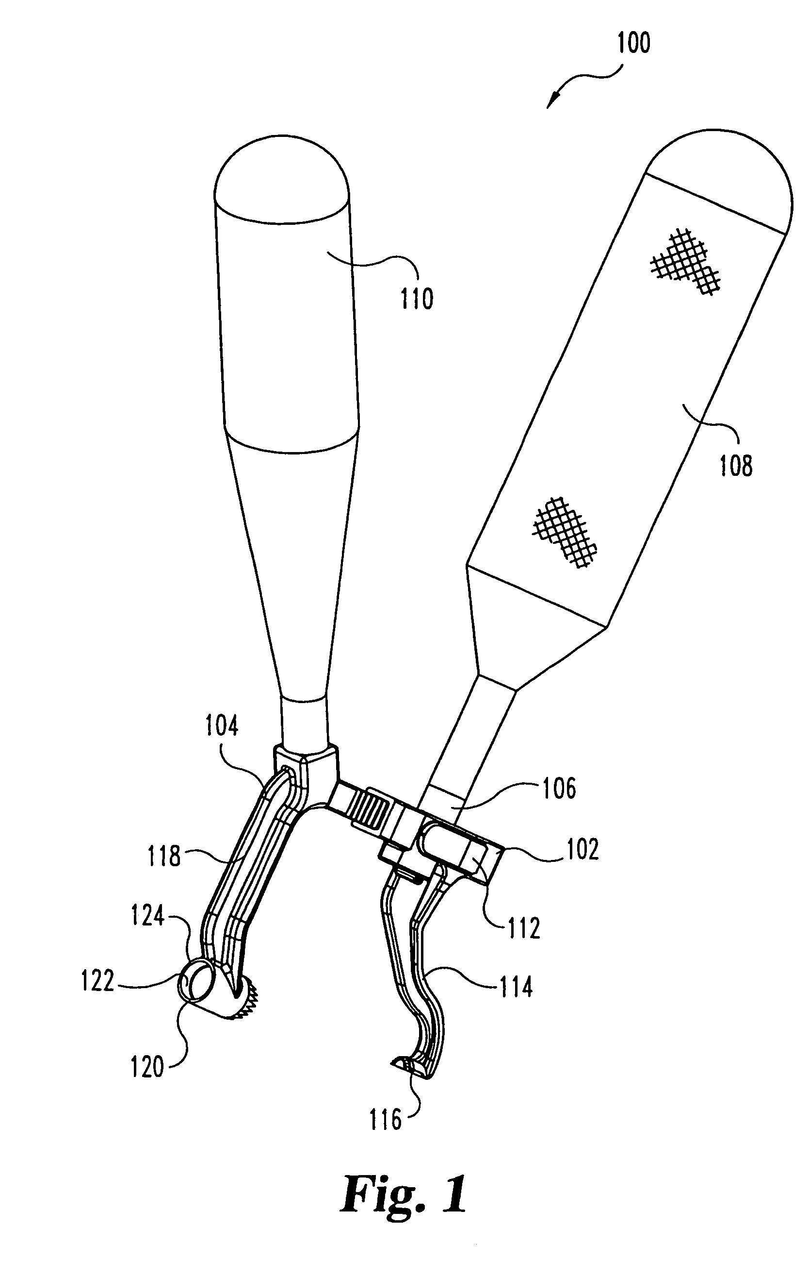
[0045]FIG. 1 shows a perspective view of a screw placement guide 100 according to one embodiment of the present invention. The placement guide 100 includes a first (driving) member 102, and a sec...


PUM


Abstract

A screw placement guide includes a first member having a first guide adapted to contact a first vertebral bone portion and a second member having a second guide adapted to contact a second vertebral bone portion. A clamping mechanism provided on one of the members clamps the first guide and the second guide to the vertebral bone portions. The first guide and the second guide are aligned in order to indicate how a fastener will be aligned when fastened between adjacent vertebrae. A driver engages clamping mechanism to clamp the two members together.

Description

REFERENCE TO RELATED APPLICATIONS[0001]This application is a continuation U.S. patent application Ser. No. 09 / 695,004, filed Oct. 24, 2000, now U.S. Pat. No. 6,669,698, issued Dec. 30, 2003, which is hereby incorporated by reference in its entirety.BACKGROUND OF THE INVENTION[0002]The present invention generally relates to fastener guides, and more specifically, but not exclusively, concerns an apparatus and method for fixing a portion of a spine with a fastener.[0003]In the realm of orthopedic surgery, it is well known to use screws to fix the position of bones. In this way, the healing of a broken bone can be promoted and malformation or other injuries can be corrected. For example, in the field of spinal surgery, there are a number of reasons for fixing a portion of the spine with screws, including (a) to correct abnormal curvature of the spine, including a scoliotic curvature, (b) to maintain appropriate spacing and provide support to broken or otherwise injured vertebrae, and (...

Claims


Application Information

Patent Timeline
Patent Type & Authority Patents(United States)
IPC IPC(8): A61B17/56A61B17/00A61B17/16A61B17/17A61B17/88A61B19/00
CPCA61B17/1615A61B17/1655A61B17/1671A61B17/8891A61B17/1757A61B2019/462A61B2017/0046A61B2090/062
Inventor TROMANHAUSER, SCOTT G.BERRY, BRET M.LANGE, ERIC C.RAY, III, EDDIE F.
Owner WARSAW ORTHOPEDIC INC
Why Eureka
Try Eureka