Exposure apparatus for posterior spinal minimally invasive screw placement surgery

a technology for exposing equipment and screw placement, which is applied in the field of medical appliances, can solve the problems of limited development at spine surgery, not widely applied and popularized, etc., and achieve the effect of accurate, fast and convenient pedicle screw placement, and easy and non-invasive reach of screw placement position

Inactive Publication Date: 2015-12-24
JIANGSU PROVINCE HOSPITAL
View PDF4 Cites 3 Cited by
  • Summary
  • Abstract
  • Description
  • Claims
  • Application Information

AI Technical Summary

Benefits of technology

[0006]An aspect relates to an exposure apparatus which can assist to accurately, quickly and conveniently conduct pedicle screw placement during a posterior minimally invasive screw placement surgery, wherein the apparatus can be used to separate a gap between a multifidus muscle and a longissimus muscle under direct vision, and can easily and non-invasively reach a screw placement position on a pedicle. Meanwhile, during a screw placement operation, the distal end of the transverse process retractor can straddle above the transverse process and is antagonistically tractive with the facet joint retractor so as to leave a sufficient space for the screw placement operation and to prompt a needle inlet point and direction for placing the pedicle screw.
[0007]A further aspect relates to an exposure apparatus for posterior spinal minimally invasive screw placement surgery according to embodiments of the present invention including a transverse process retractor and a facet joint retractor used cooperatively with the transverse process retractor, the transverse process retractor consists of a first handle and a first retractor body, wherein the first retractor body is an L-shaped metal bar having an included angle of 100±10 degrees, which satisfies the demand of externally extending 10 to 15 degrees during screw placement, and facilitates the placement of the pedicle screw; one end of the first retractor is fixedly connected to the first handle, the other end of the first retractor bends towards the direction of the first handle, and the end is provided with a crescent type recess, so that the transverse process retractor can easily straddle above the transverse process during the surgery and is located in the center of the transverse process; the facet joint refractor consists of a second handle and a second refractor body, wherein the second retractor body is an L-shaped metal bar having an included angle of 80±10 degrees, which satisfies the demand of the characteristic of holding multifidus muscle between the inside of an approach and the spinous process as well as externally extending 10 to 15 degrees during screw placement, facilitates the exposure of a surgical approach during surgery, and protects the inside muscle and facilitates the placement of the pedicle screw; one end of the second retractor body is fixedly connected to the second handle, the other end of the second retractor body bends towards the direction of the second handle, and the end is provided with a crescent type recess, so that a screw placement position can be easily exposed, and injury of local facet joint caused by contact of the retractor will not be increased.
[0008]As a further improvement of the foregoing technical solution, both the first retractor body and the second refractor body include a horizontal segment and a vertical segment, wherein a folded angle of 16S±15 degrees is formed between the first handle and the second handle, and the horizontal segment thereof, both the first handle and the second handle are located at one side of the horizontal segment opposite to the vertical segment so as to be convenient for holding during traction in the surgery, and reduce the influences of tissues surrounding an incision placing the retractor; the other ends of the first retractor body and the second retractor body respectively bend by 10±10 degrees towards the directions of the first handle and the second handle respectively, and the bending lengths of the first retractor body and the second retractor body are 5±3 mm.

Problems solved by technology

But presently, it has not been widely applied and popularized for being applied in clinic for almost 30 years since it is invented due to the expensive supporting instruments and relatively flat learning curves, and particularly, it is only limited to be developed at the spine surgery of tertiary hospitals at home presently.

Method used


Image

  • Exposure apparatus for posterior spinal minimally invasive screw placement surgery
  • Exposure apparatus for posterior spinal minimally invasive screw placement surgery
  • Exposure apparatus for posterior spinal minimally invasive screw placement surgery

Examples


embodiment 1

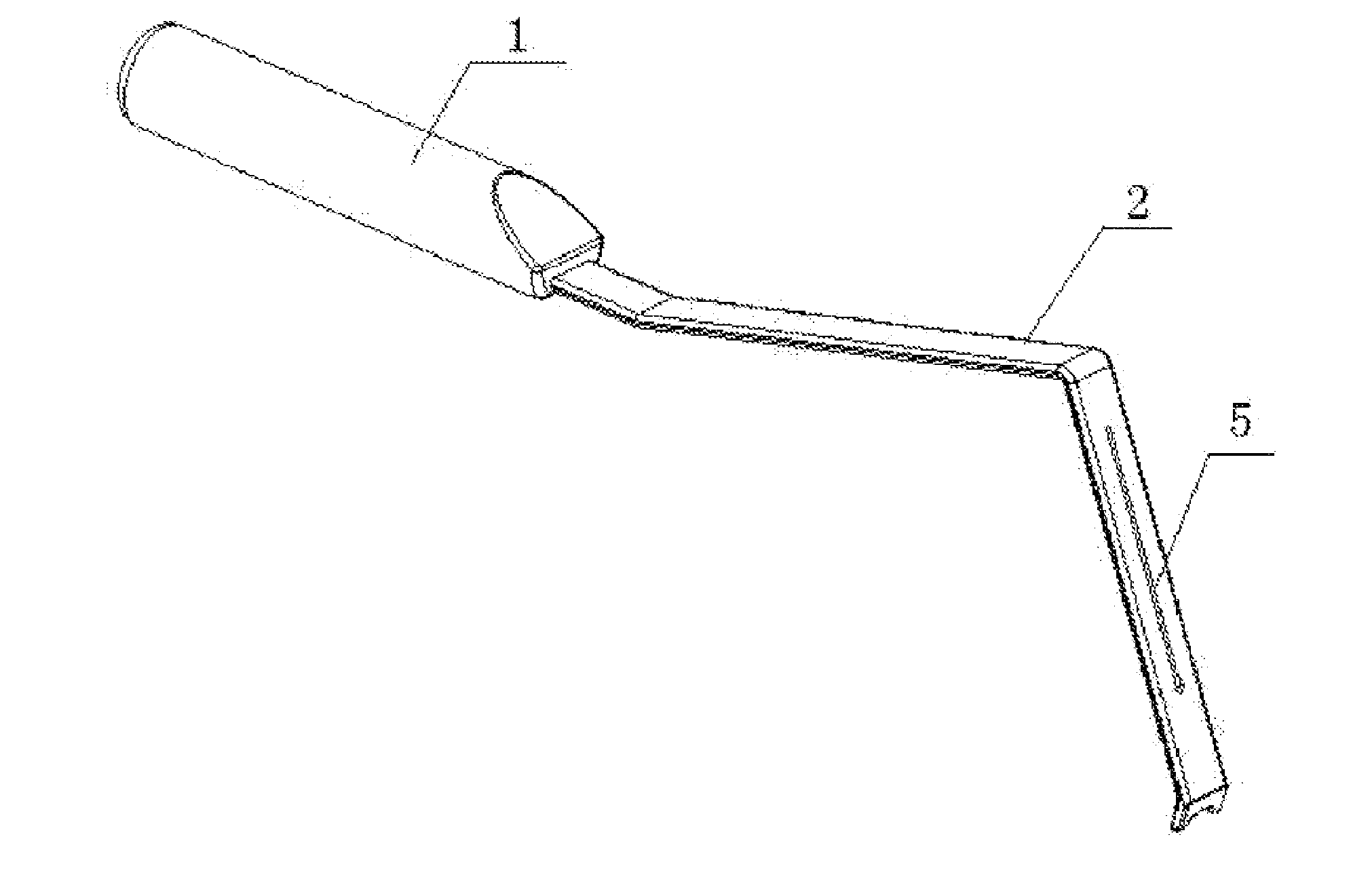
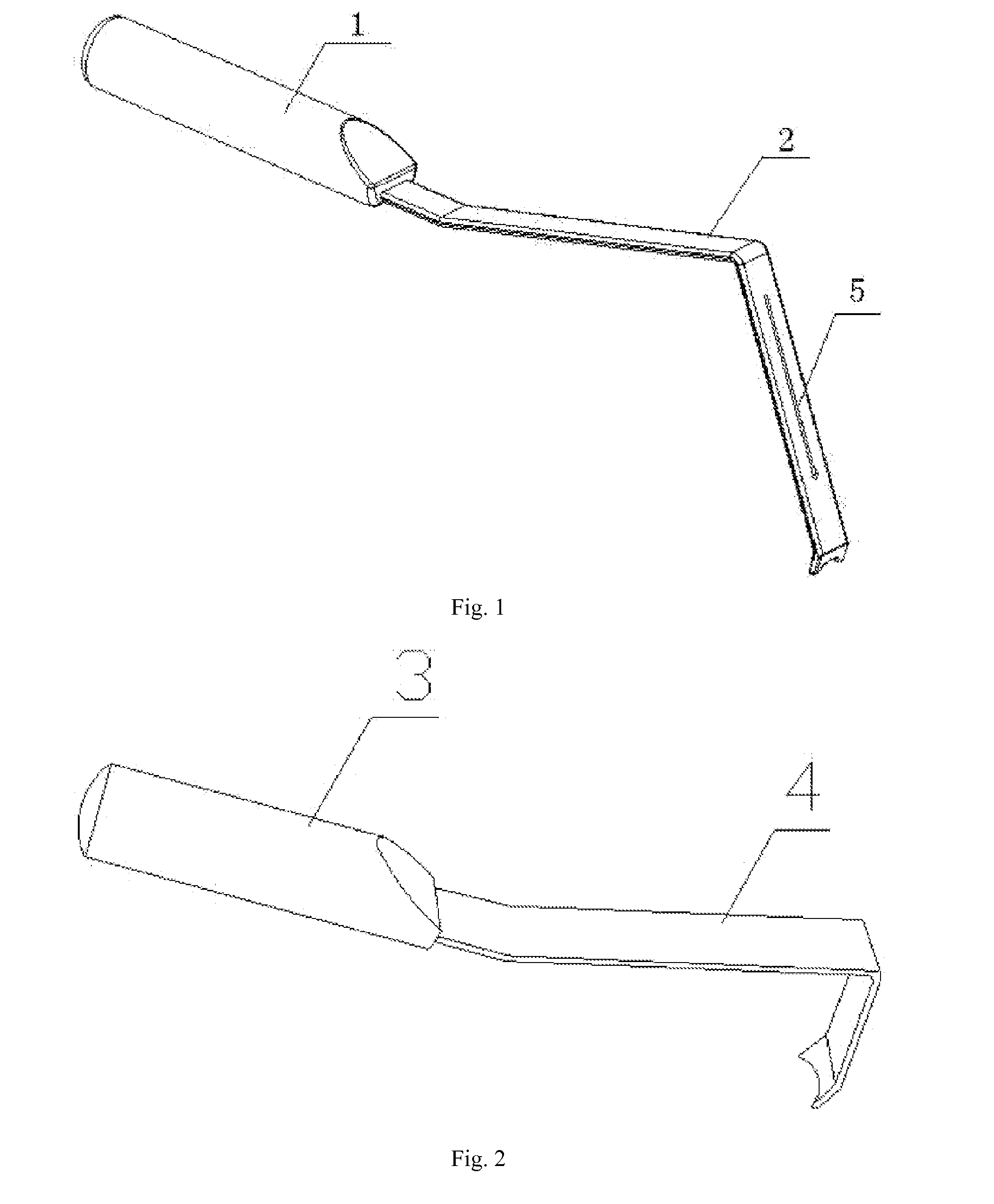
[0024]as shown in FIG. 1 and FIG. 2, an exposure apparatus for posterior spinal minimally invasive screw placement surgery includes a transverse process retractor and a facet joint retractor used cooperatively with the transverse process retractor.

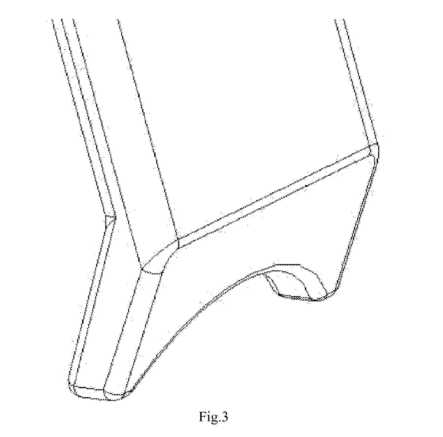
[0025]The transverse process retractor consists of a first handle 1 and a first retractor body 2, wherein the first retractor body 2 is an L-shaped metal bar having an included angle of 100 degrees, one end of the first retractor body 2 is fixedly connected to the first handle 1, the other end of the first retractor bends towards the direction of the first handle 1, and the end is provided with a crescent type recess.

[0026]The facet joint retractor consists of a second handle 3 and a second retractor body 4, wherein the second retractor body 4 is an L-shaped metal bar having an included angle of 80 degrees, one end of the second retractor body 4 is fixedly connected to the second handle 3, the other end of the second retractor body bends t...


PUM


Abstract

An exposure apparatus for posterior spinal minimally invasive screw placement surgery includes a transverse process refractor and a facet joint retractor, is provided. The apparatus separates a gap between a multifidus muscle and a longissimus muscle, easily and atraumatically reach a screw placement position on a pedicle, accurately place the retractors, and thereafter locally form a screw placement tunnel space that externally extends 10 to 15 degrees. During a screw placement operation, the distal end of the transverse process refractor can straddle above the transverse process and is antagonistically tractive with the facet joint retractor so as to leave a sufficient space for the screw placement operation and to prompt a needle inlet point and direction for placing a pedicle screw. The distal end of the refractor employs a design of a recessed crescent type, protects local soft tissues during traction, and prevents the tissues from damage.

Description

CROSS-REFERENCE TO RELATED APPLICATIONS[0001]This application claims priority to PCT Application No. PCT / CN2013 / 087037, having a filing date of Nov. 13, 2013, based off of Chinese Application No. 201310035400.1, having a filing date of Jan. 30, 2013 the entire contents of which are hereby incorporated by reference.TECHNICAL FIELD OF TECHNOLOGY[0002]The following invention relates to an exposure apparatus for posterior spinal minimally invasive screw placement surgery, which belongs to the field of medical appliances.BACKGROUND OF THE INVENTION[0003]Pedicle screw technology has been developed quickly since its introduction in 1980s and has been widely used in surgical treatment on affections such as spinal degeneration, spondylolisthesis, spinal stenosis, vertebral fracture, malformation, metastatic tumor of bone, spinal instability and the like. At present, the pedicle screw is one of the internal fixation instruments most widely used in a spine surgery, and methods for embedding th...

Claims


Application Information

Patent Timeline
Patent Type & Authority Applications(United States)
IPC IPC(8): A61B17/02
CPCA61B17/0218A61B2017/0256A61B17/025A61B17/02A61B2090/0807
Inventor CAO, XIAOJIANLI, HAIJUNTANG, JIANXIE, HAO
Owner JIANGSU PROVINCE HOSPITAL
Why Eureka
Try Eureka