
Monitoring and recording tag with RF interface and indicator for fault event

a technology of fault event and recording tag, which is applied in the direction of instruments, heat measurement, and burglar alarm mechanical actuation, etc., can solve the problem of teaching a quite complex communication scheme and is undoubtedly a very expensive tag

Active Publication Date: 2006-06-13
PHENIX LONGHORN LLC
View PDF18 Cites 52 Cited by
  • Summary
  • Abstract
  • Description
  • Claims
  • Application Information

AI Technical Summary

Benefits of technology

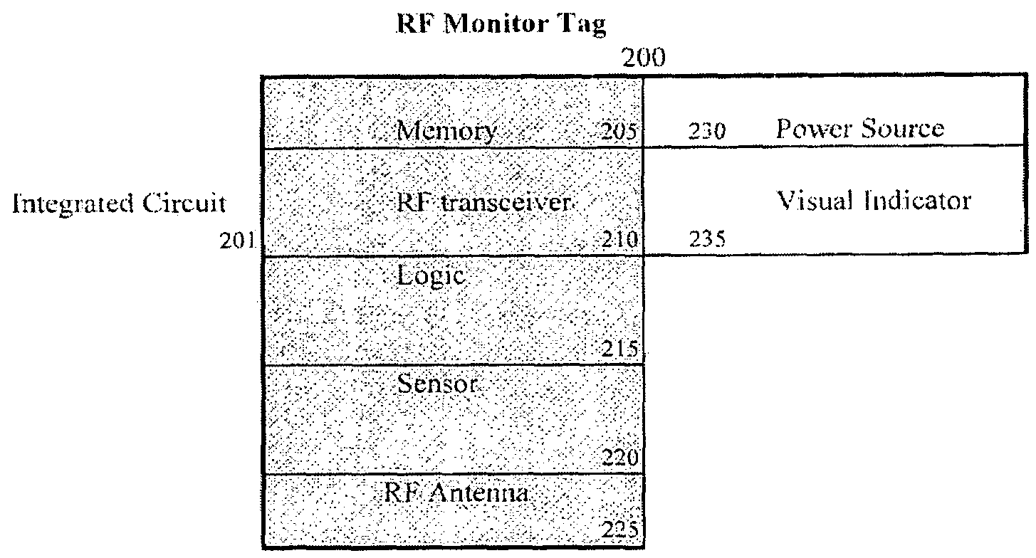
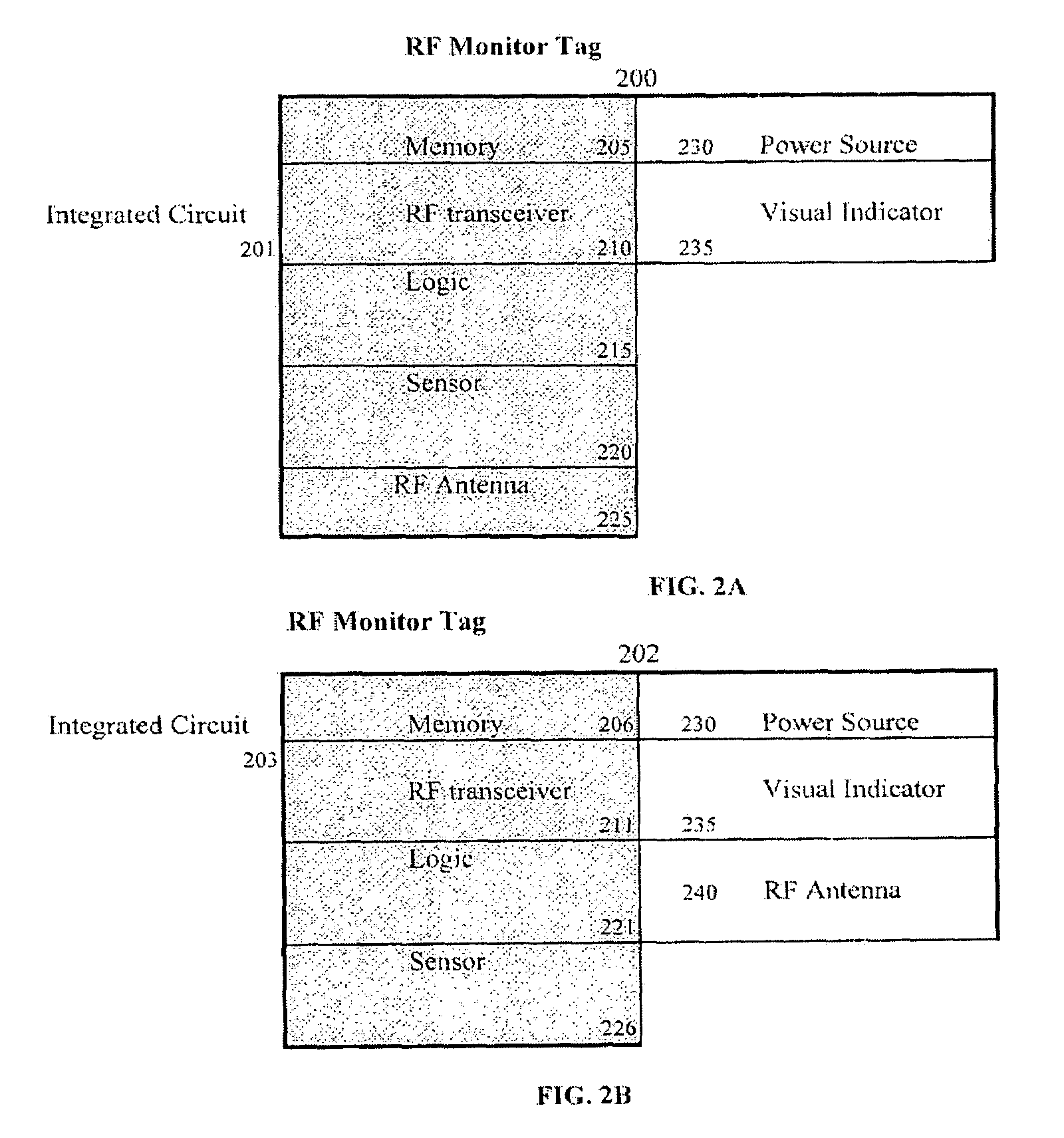
[0006]A single integrated circuit provides RF communicating capability, sensing and recording of one or more conditions critical to the entity to which it is attached. The chip is part of a larger module comprising a visual indicator, such as an LED, and a power source such as a battery. The sensor may be a temperature sensor whose output is stored in a non-volatile and rewritable memory section of the chip on some periodic basis. Based upon the sens

Problems solved by technology

The '417 patent also teaches a quite complex communication scheme; undoubtedly a very expensive tag.

Method used


Image

  • Monitoring and recording tag with RF interface and indicator for fault event
  • Monitoring and recording tag with RF interface and indicator for fault event
  • Monitoring and recording tag with RF interface and indicator for fault event

Examples


Embodiment Construction

[0010]The RF Monitor tag device consists of an integrated circuit 201 or 203; a visual indicator 235, such as an LED, a liquid crystal display, a TFT display, or a light bulb; a power source 230, such as a lithium battery; and an RF antenna encapsulated into a molded tag; optionally the antenna may be on the integrated circuit. The integrated circuit provides multiple functions including communication via the RF transceiver section, logic for interpreting commands, environmental monitoring, timekeeping and time-of-day recording, storage of the sensor readings, a product identifier, manufacturing history and other information relevant to the user.

[0011]The monitor contains an integrated radio frequency or RF interface which provides a communication link to the tag without requiring an electrical connection or close proximity; distances greater than 10 meters are achievable. This interface is used to initialize the tag during product pack and ship as well as to read out the sensor his...


PUM


Abstract

A single integrated circuit provides communication, sensing and recording of one or more conditions critical to the entity to which it is attached. The chip is part of a larger module comprising a visual indicator, such as an LED, and a power source such as a battery. The sensor may be a temperature sensor whose output is stored in a non-volatile memory section of the chip on some periodic basis. A product identifier is stored on the chip; a method for product recall or location is described.

Description

[0001]This application claims priority from U.S. Provisional Application Ser. No. 60 / 424,308 filed on Nov. 7, 2002.FIELD OF INVENTION[0002]Invention relates to a method of recording a sensor reading over an extended period of time and more particularly to communicating the contents of an alarm condition via radio frequency or a visual indicator.BACKGROUND OF INVENTION[0003]RF tags have come into use lately as a means of identification which can be remotely sensed. U.S. Pat. No. 6,563,417 describes an RFID tag mountable to a product or product carrier. The RFID tag contains different chips for computing, storage and sensing, as well as a battery and radio transceiver. The '417 patent also teaches a quite complex communication scheme; undoubtedly a very expensive tag.[0004]There exists a need for a very inexpensive, even disposable, RF tag which can monitor one or more conditions in the environment and communicate in some manner when those conditions have exceeded some predetermined l...

Claims


Application Information

Patent Timeline
IPC IPC(8): G08B13/14
CPCG01K1/02G01K1/022G08B25/10G08B13/2462G08B21/18G01K1/024
Inventor ORLANDO, RICHARD V.BLYTH, TREVOR A.
Owner PHENIX LONGHORN LLC
Learn More