Image processing apparatus and image processing method

Inactive Publication Date: 2006-06-13
CANON KK
View PDF7 Cites 5 Cited by
  • Summary
  • Abstract
  • Description
  • Claims
  • Application Information

AI Technical Summary

Benefits of technology

[0008]The present invention was conceived with the above-described conventional examples in mind, and has as its object to provide a simple, low-cost and effective image processing appara

Problems solved by technology

However, although the conventional apparatus described above can correct the overall magnification, as shown in FIG. 2, with a focusing optical system having partial magnification characteristics, correcting the overall magnification to fit the image periphery means that th

Method used


Image

  • Image processing apparatus and image processing method
  • Image processing apparatus and image processing method
  • Image processing apparatus and image processing method

Examples


first embodiment

[0027]A detailed description will now be given of an image processing apparatus according to the present invention, with reference to FIGS. 4, 5, 6 and 7.

[0028]FIG. 4 is a schematic diagram of an image processing apparatus according to a first embodiment of the present invention. FIG. 5 is a flow chart showing steps in an operation performed by an image processing apparatus according to a first embodiment of the present invention. FIG. 6 shows partial magnification of an image by an image processing apparatus according to a first embodiment of the present invention.

[0029]FIG. 7 shows read image and image output by an image processing apparatus according to a first embodiment of the present invention.

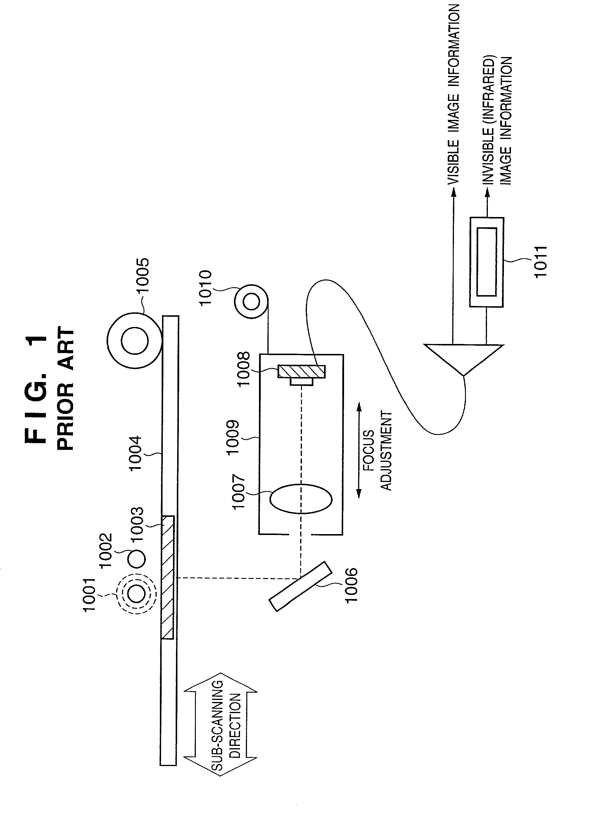
[0030]As shown in the diagram, image information of a transparent film 103 that is illuminated by an invisible (infrared) light source 101 and a visible light source 102 is reflected by a mirror 106, passed through a lens 107 and formed into an image (that is, focused) on a line CCD that...

second embodiment

[0055]FIG. 8 is a schematic diagram of an image processing apparatus according to the present invention, more specifically of the essential parts of a so-called flathead scanner integrated with the carriage.

[0056]The image information of a film 403 that is a transparent medium which is illuminated by either an infrared light source 401 or a visible light source 402 is reflected by a plurality of mirrors 406 and passed through a focusing lens 407 to focus on a line CCD 408 arranged in a main scanning direction. The film 403 is mounted on a film glass 404.

[0057]The reflecting mirror 406, the focusing lens 40, the line CCD 408 and a focus correction unit 409 to be described in detail later are all disposed within a carriage 410. The carriage 410 is driven in a sub-scanning direction by a drive unit 405 and the images recorded on the film 403 are read as two-dimensional image information by the line CCD 408.

[0058]Additionally, the point of focus of the infrared light source 401 and the ...

third embodiment

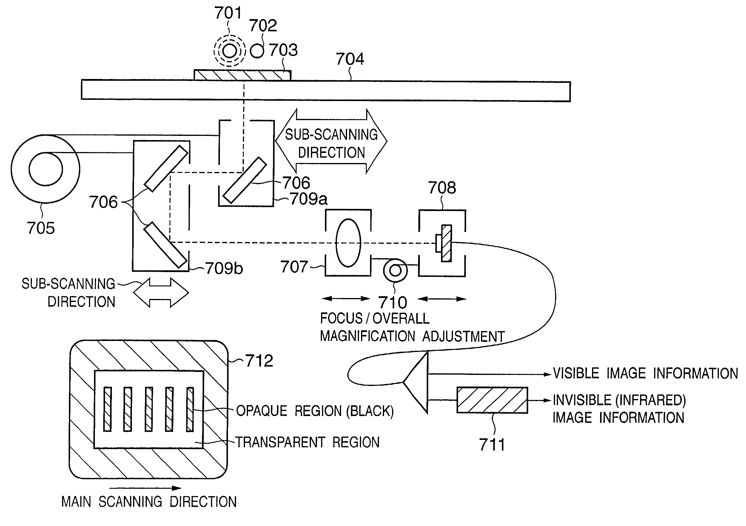
[0070]FIG. 11 is a schematic diagram of an image processing apparatus according to the present invention. FIG. 12 shows partial magnification of an image by an image processing apparatus according to a third embodiment of the present invention. FIG. 13 shows read image and image output by an image processing apparatus according to a third embodiment of the present invention.

[0071]The image information of a film 703 that is a transparent medium which is illuminated by either an infrared light source 701 or a visible light source 702 is reflected by a plurality of mirrors 406 and passed through a focusing lens 707 to focus on a line CCD 708 arranged in a main scanning direction. The film 703 is mounted on a film glass 704.

[0072]Of the reflecting mirrors 706, that which is closest to the film 703 is mounted on a first mirror mount 709a. The remaining two mirrors are mounted on a second mirror stand 709b. The respective mirror bases are moved by a drive unit 705 in the sub-scanning dire...


PUM


Abstract

An image processing apparatus for processing visible image information and invisible image information obtained from visible light and invisible light directed onto an original and from the original onto an image pick-up element via a focusing optical system. The image processing apparatus includes an infrared light source, a visible light source, a focus correction unit that corrects the focus of the images when the images are formed on the image pick-up element and acquired, and a signal processor that corrects a partial magnification difference between the visible image and the infrared image.

Description

FIELD OF THE INVENTION[0001]The present invention relates generally to an image processing apparatus and an image processing method, and more particularly, to an image processing apparatus and an image processing method for processing visual image information and invisible infrared image information obtained by directing both visible light and invisible infrared light that has passed through a transparent original onto a fixed image pick-up element via an image formation system.BACKGROUND OF THE INVENTION[0002]In the image reading apparatuses that convert image information of a transparent original into electrical signals which are then read into a computer, film scanners such as those described in Japanese Laid-Open Patent Application Nos. 2000-324303 and 2001-189833 have been proposed, as apparatuses that use infrared light (which cannot be seen) to acquire dust and scratch mark information and to correct those portions of the visible image information that correspond to the locat...

Claims


Application Information

Patent Timeline
IPC IPC(8): G06K9/40H04N1/04G06T5/00G06T5/50H04N1/409
CPCG06T5/50H04N1/4097G06T5/005G06T2207/10048G06T2207/10008
Inventor HAYASHIDE, TADAO
Owner CANON KK
Why Eureka
Try Eureka