Interior member having an airbag door section for use in vehicles, and its molding method

a technology of interior member and airbag door section, which is applied in the direction of vehicle components, pedestrian/occupant safety arrangements, other domestic objects, etc., can solve the problems of insufficient thinness of resin, inability to maintain the quality of outer appearance, and difficulty in making the line in the break portion invisible, so as to reduce the break force of the break portion

Inactive Publication Date: 2006-06-20
TOYOTA JIDOSHA KK
View PDF71 Cites 22 Cited by
  • Summary
  • Abstract
  • Description
  • Claims
  • Application Information

AI Technical Summary

Benefits of technology

[0048]Accordingly, the impact load from the bag body of the air bag is concentrated at the center portion of the tear portion when the bag body of the air bag is expanded, since the push-up means is provided. Further, since the resin fluidizing boundary is set at the core back area which is for forming the break portion when

Problems solved by technology

However, in this method, it is very difficult to make the line in the break portion invisible while maintaining a predetermined break force.
That is, when the thickness of the resin is made thin, the line and the undulation in the break portion are seen from the outer appearance side even in a case wherein a relief groove is provided, so that the quality of the outer appearance can not be maintained, and the thickness of the resin can not be made sufficiently thin.
When it is difficult to expand the door portion due to the increased break force required during expansion at the break portion (tear portion), which is formed at the air bag door portion, and in order to ameliorate this the thickness of the resin in the break portion is made too thin, the thin portion becomes visible from an outer side and s

Method used


Image

  • Interior member having an airbag door section for use in vehicles, and its molding method
  • Interior member having an airbag door section for use in vehicles, and its molding method
  • Interior member having an airbag door section for use in vehicles, and its molding method

Examples


first embodiment

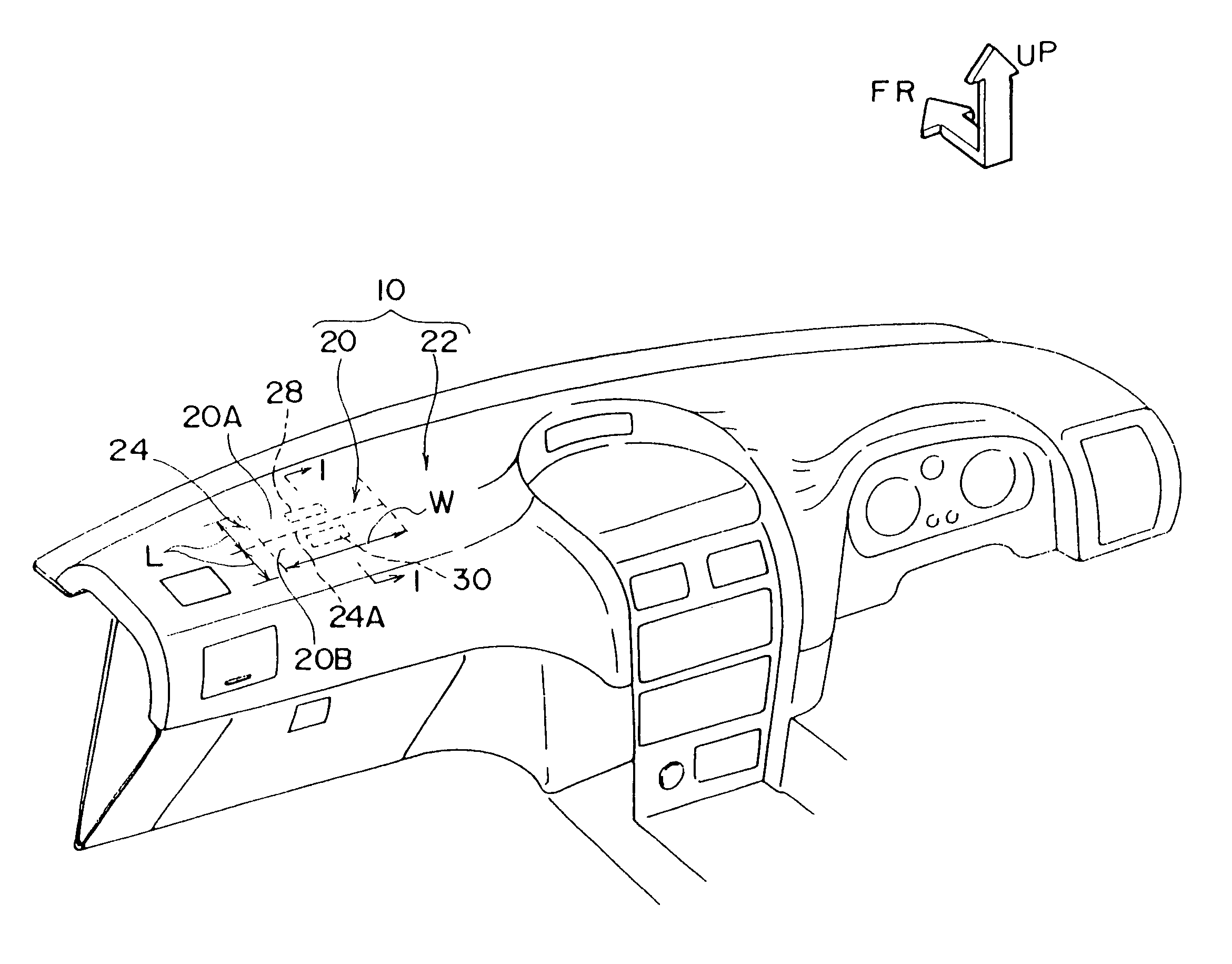
[0115]a interior member for an automotive vehicle having an air bag door portion in accordance with the present invention will be described below with reference to FIGS. 1 to 4.

[0116]Here, in the drawings, an arrow FR indicates a forward direction of an automotive vehicle, and an arrow UP indicates an upward direction an the automotive vehicle.

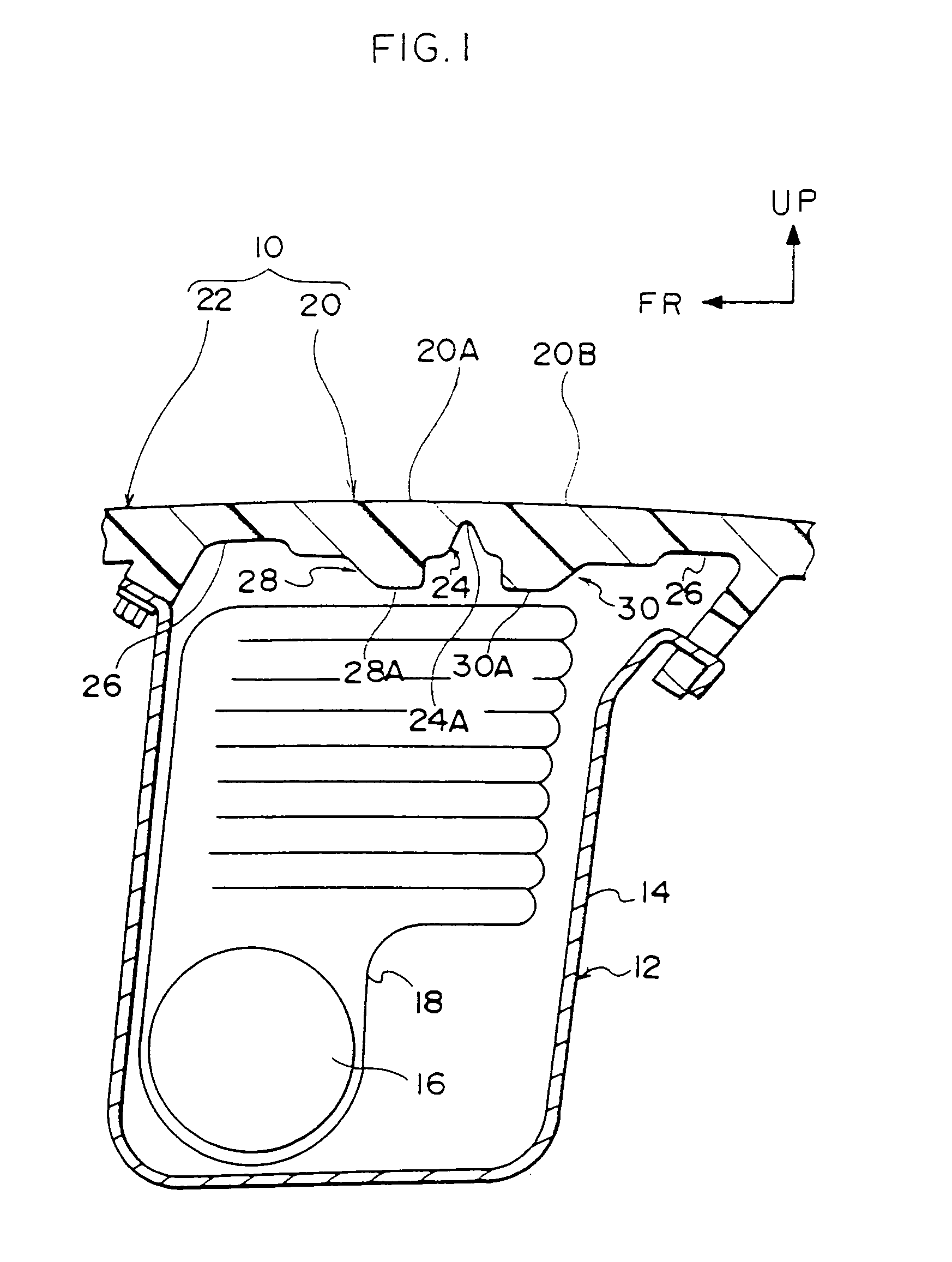
[0117]As shown in FIG. 1, in an instrument panel 10, which is a trim member for an automotive vehicle provided within a vehicle cabin of the automotive vehicle, an air bag apparatus 12 is arranged inside an assistant driver's seat. An air bag case 14 for this air bag apparatus 12 is fixed to an instrument panel reinforcement (not shown), and an inflator 16 and a air bag body 18 in a folded state is contained within the air bag case 14.

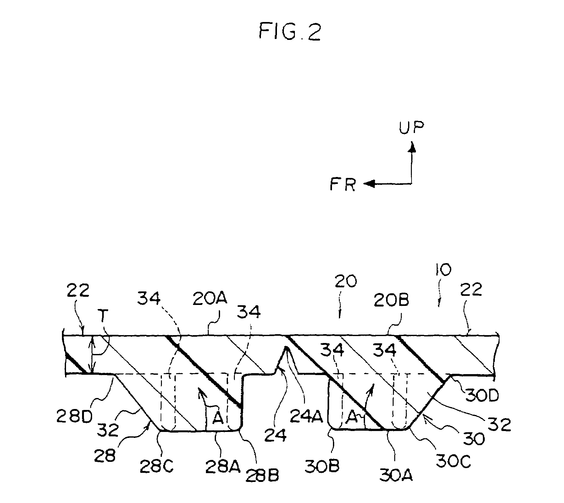
[0118]Further, a portion in a position substantially opposite to that of the air bag case 14 of the instrument panel 10 serves as an air bag door portion 20, and a portion other than the air bag door portion 20 o...

second embodiment

[0132]Next, a interior member for an automotive vehicle having an air bag door portion will be described below with reference to FIGS. 7 to 9.

[0133]In this case, the same reference numerals are attached to the same elements as those in the first embodiment, and an explanation thereof will be omitted.

[0134]As shown in FIG. 7, in this second embodiment, metal plates 36 and 38 made of a metal, for example, aluminum, iron, stainless steel or the like, are respectively disposed below the front door portion 20A and the rear door portion 20B of the air bag door portion 20. A front end portion 36A of the metal plate 36 is fastened to both the air bag case 14 and the main body portion 22 of the instrument panel 10 by a bolt 40 passing through a mounting hole 39 punched into the metal plate 36. A rear end portion 38A of the metal plate 38 is fastened to both the air bag case 14 and the main body portion 22 of the instrument panel 10 by a bolt 42 passing through a mounting hole 41 punched into...

third embodiment

[0139]Next, a interior member for an automotive vehicle having an air bag door portion will be described below with reference to FIGS. 12 and 13.

[0140]In this case, the same reference numerals are attached to the same elements as those in the first embodiment, and an explanation thereof will be omitted.

[0141]As shown in FIG. 12, in this third embodiment, metal plates 48 and 50 made of a metal, for example, aluminum, iron, stainless steel or the like are respectively disposed below the front door portion 20A and the rear door portion 20B of the air bag door portion 20. A front end portion 48A of the metal plate 48 is fixed to the air bag case 14 by a bolt 51 and a nut 52 and a rear end portion 50A of the metal plate 50 is fixed to the air bag case 14 by a bolt 53 and a nut 54. Further, hinge portions 48B and 50B of the metal plates 48 and 50 are made thin. The hinge portions 48B and 50B are off set below the hinge portions 26 of the air bag door portion 20 (with off-set amounts H1 an...


PUM

PropertyMeasurementUnit
Stiffnessaaaaaaaaaa

Abstract

A tear portion is formed at a substantially center portion in a longitudinal direction and at both end portions in a lateral direction of an air bag door portion of an instrument panel so as to be formed in an H shape in a plan view. In the air bag door portion, protrusions are protruded downward at positions at both sides in a longitudinal direction of an automotive vehicle having therebetween a center portion of the tear portion, these protrusions being integrally formed with the air bag door portion. Accordingly, it is structured such that during expansion of the air bag body, the expanding air bag body abuts lower surfaces of the protrusions, so as to press the protrusions upward. Therefore, even in a case wherein the air bag door portion and the main body portion of the trim member for the automotive vehicle are formed of the same resin, a quality of an outer appearance is not deteriorated, and a break force of a break portion of the air bag door portion is reduced to a desired value.

Description

[0001]This is a Division of application Ser. No. 10 / 396,554 filed Mar. 26, 2003 now U.S. Pat. No. 6,733,713, which in turn is a Division of application Ser. No. 09 / 194,355 filed Nov. 20, 1998 now U.S. Pat. No. 6,612,607 B1 issued Sep. 2, 2003, which is a National Stage of International Application No. PCT / JP98 / 01207 filed Mar. 20, 1998. The entire disclosure of the prior applications is hereby incorporated by reference herein in its entirety.BACKGROUND OF THE INVENTION[0002]Conventionally, as an interior member of an automotive vehicle having an air bag door portion such as an instrument panel, a door trim, a center pillar and the like, there has been known a structure described in Japanese Patent Application Laid-Open (JP-A) No. 8-192666.[0003]In the instrument panel having the air bag door portion disclosed in the above publication, a main body portion of the instrument panel and the air bag door portion are integrally formed by so-called dual-injection molding (double injection m...

Claims


Application Information

Patent Timeline
IPC IPC(8): B60R21/16B29C45/00B29C45/56B60R21/2165B60R21/217
CPCB29C45/0081B29C45/56B60R21/2165B60R21/2171B60R2021/2172B29L2031/3038B60R21/20B60R21/16
Inventor TAKAHASHI, HIDEAKI
Owner TOYOTA JIDOSHA KK
Why Eureka
Try Eureka