Cathedral door shutter assembly

a cathedral door and shutter assembly technology, applied in the field of drawout circuit breakers, can solve the problems of not being able to fit within the enclosure of smaller circuit breakers, not being able to have overly complex mechanisms, and not being able to have metal parts disposed adjacent to circuit breaker fingers and conductors

Inactive Publication Date: 2006-06-20
EATON CORP
View PDF22 Cites 6 Cited by
  • Summary
  • Abstract
  • Description
  • Claims
  • Application Information

AI Technical Summary

Benefits of technology

[0012]In operation, each door member moves between a first, closed position and a second, open position. The door members are disposed between the conductors and the front of the enclosure. Each door member is coupled to the closing device which biases the door member to the first, closed position. Thus, when the circuit breaker is out of the housing assembly, the door members are in the first, closed position. As a circuit breaker is moved into the housing assembly, the finger connectors engage the door members and move the door members to the second, open position. As the door members are opened, the flexibility of the return spring allows the rod to move along the generally arcuate path the doors travel. When the circuit breaker is removed from the housing assembly, the finger connectors disengage from the door members and the closing device moves the door members to the first position.

Problems solved by technology

It is not desirable to have metal parts disposed adjacent to the circuit breaker fingers and conductors.
Further, it is not desirable to have overly complex mechanisms for performing the simple operation of opening and closing the shutter assembly.
Additionally, because the shutter door assembly included space for the shutter to slide laterally, the shutter assembly has a lateral width that may not fit within enclosures for smaller circuit breakers.

Method used


Image

  • Cathedral door shutter assembly
  • Cathedral door shutter assembly
  • Cathedral door shutter assembly

Examples


first embodiment

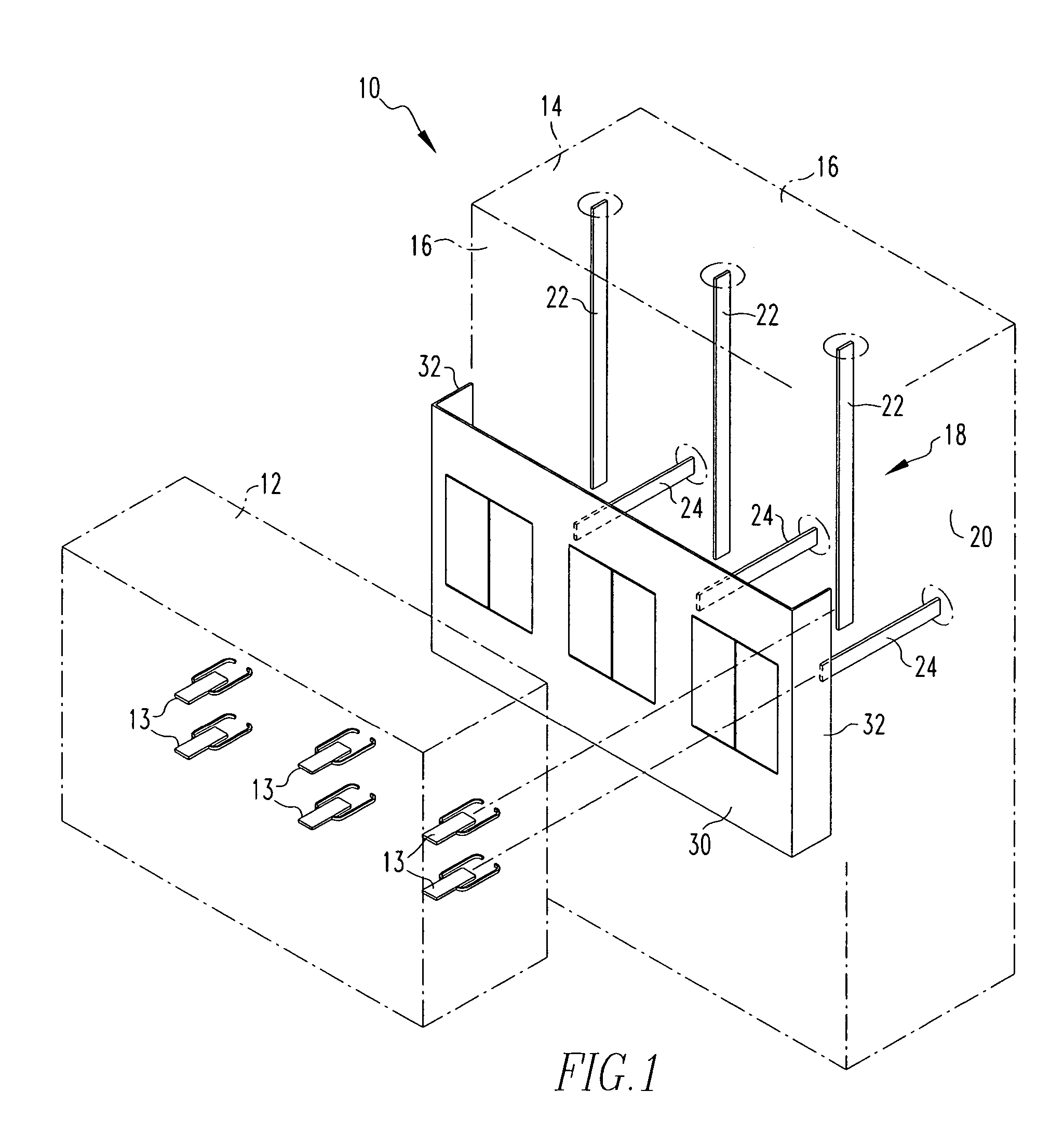
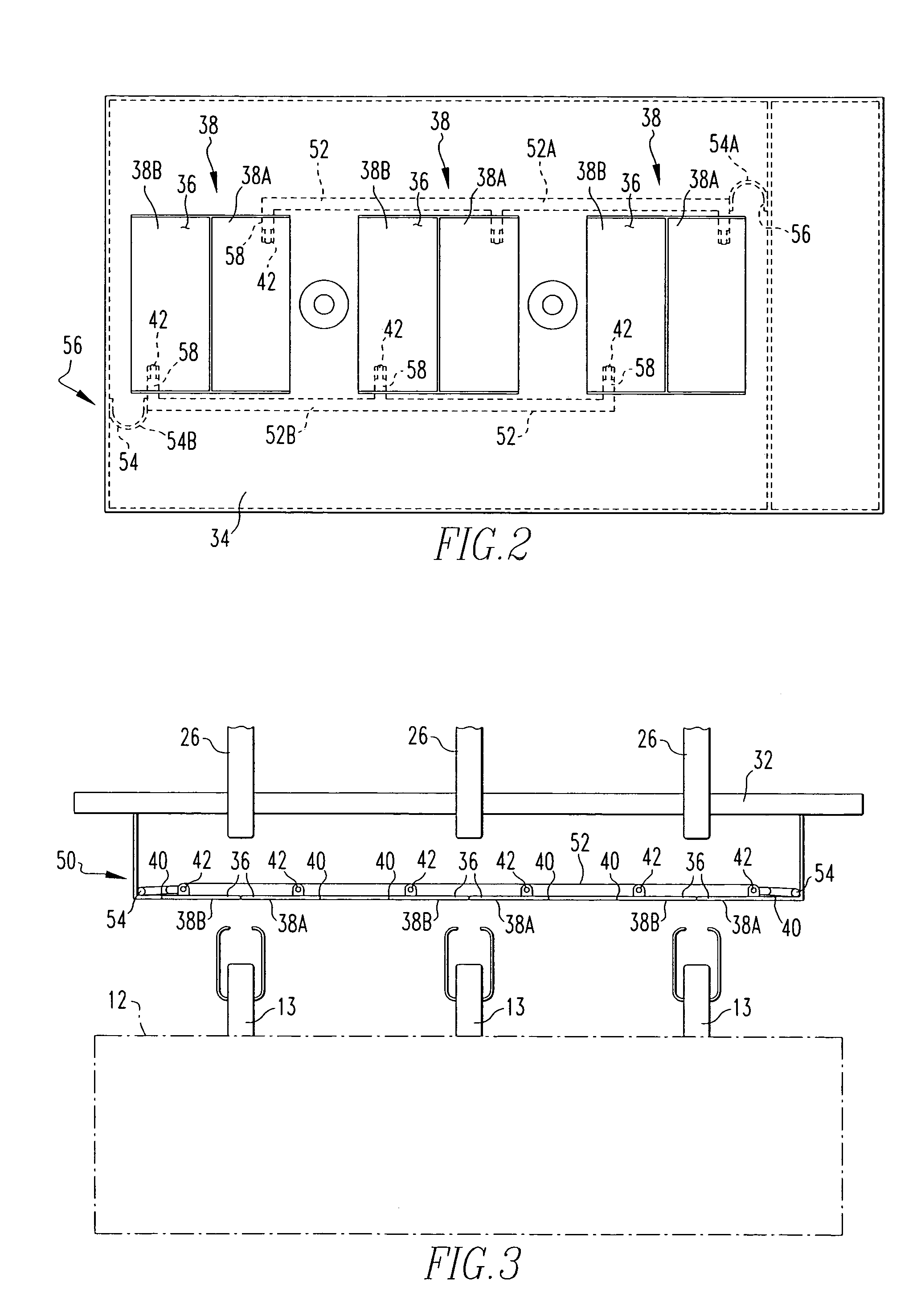
[0023]As shown in FIGS. 2 and 3, the shutter assembly 30 includes a mounting assembly 32, a door panel 34, at least one opening 36, at least one door member 38 disposed in each opening 36, and a closing device 50. The mounting assembly 32 is coupled to the housing assembly wall members 16 or back wall 20. The mounting assembly 32 is structured to hold the door panel 34 in a location between the bus assembly 21 and the front of the housing assembly 14. The mounting assembly 32 is made from a non-conductive material. The door panel 34 is a planar member made from a non-conductive material. The door panel 34 has one opening 36 for each pole of the circuit breaker assembly 12. Each opening 36 is sized so that the opening 36 is disposed over either a line and load conductor 22, 24 for a single pole of the circuit breaker assembly 12. A door member 38 is a non-conductive planar member disposed in each opening 36 and coupled to the door panel 34 by a living hinge 40, as shown in FIG. 4. Ea...

second embodiment

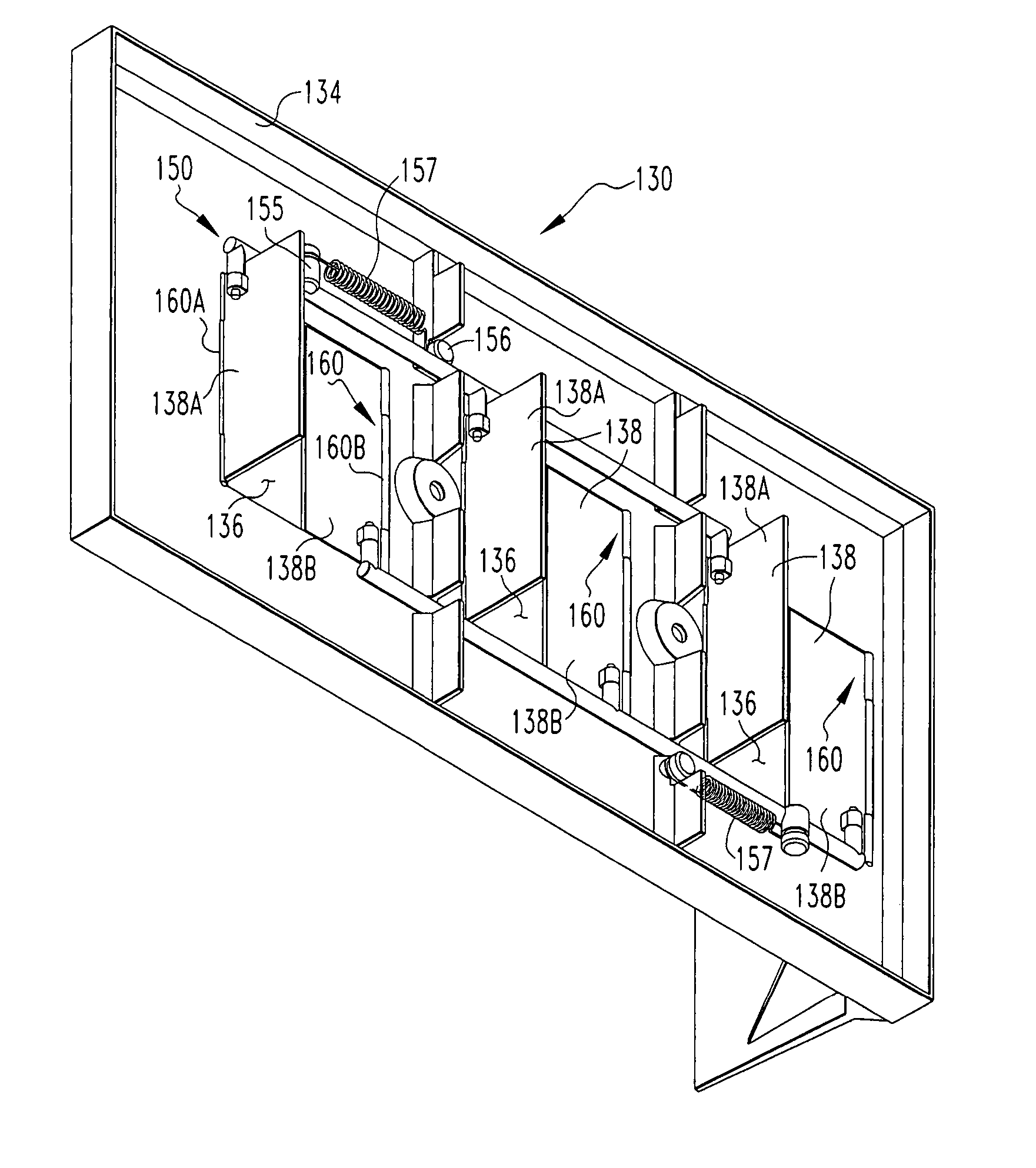
[0030]the shutter assembly 130 is shown in FIG. 6. Because this embodiment of the invention is substantially similar to the prior embodiment, except for the snap fit hinge 160, the reference numbers for like components shall be maintained except increased by 100. Thus, in this embodiment, the shutter assembly 130 includes a door panel 134, at least one opening 136, at least one door member 138 disposed in each opening 136, and a closing device 150. In this embodiment of the shutter assembly 130 the door panel 134 is coupled to a mounting assembly 32 in a manner substantially similar to the prior embodiment. The door panel 134 is a planar member made from a non-conductive material. The door panel 134 has one opening 136 for each pole of the circuit breaker assembly 12. Each opening 136 is sized so that the opening 136 is disposed over either a line or a load conductors 22, 24 for a single pole of the circuit breaker assembly 12. A door member 138 is a non-conductive planar member dis...


PUM


Abstract

A shutter assembly for a shuttered bus assembly is provided. The shuttered bus assembly is coupled to a circuit breaker housing assembly. The circuit breaker housing assembly is structured to enclose a circuit breaker assembly. The circuit breaker assembly is structured to move generally horizontally in and out of the circuit breaker housing assembly. The circuit breaker assembly has a plurality of finger connectors extending generally horizontally from the back side of the circuit breaker assembly. The shuttered bus assembly has at least one pair of conductors which extend toward the front of said housing assembly. The finger connectors are structured to engage the conductors. The shutter assembly includes a mounting assembly and a door panel. The mounting assembly is structured to be coupled to the housing assembly. The door panel has at least one opening and at least one door member, the door panel extends across the housing assembly and is disposed between the plurality of conductors and the circuit breaker assembly when the circuit breaker assembly is out of the housing assembly, the door panel is further coupled to the mounting assembly. The at least one door member is disposed in the at least one opening and is coupled to the door panel by a hinge. The door member is structured to move between a first closed position and a second open position. The door member is structured to be moved to the second position by the finger connectors as the circuit breaker assembly is moved into the housing assembly.

Description

BACKGROUND OF THE INVENTION[0001]1. Field of the Invention[0002]The present invention relates to circuit breakers, and in particular to a draw-out circuit breaker mounted in a housing assembly and, more specifically, to a housing assembly having a bus assembly mounted therein and a cathedral door shutter assembly structured to block access to the bus assembly when the circuit breaker is removed from the housing assembly.[0003]2. Background Information[0004]Low voltage circuit breakers used in electric power distribution systems are commonly mounted in a housing assembly and supported on rollers which permits easy installation and removal of the sizeable circuit breakers required for such service. The housing assembly has walls forming an enclosure and a bus assembly. The bus assembly includes line and load conductors for each pole of the circuit breaker. Each line conductor, or “riser,” is, essentially, an elongated conductive bar with the longitudinal axis extending vertically thro...

Claims


Application Information

Patent Timeline
Patent Type & Authority Patents(United States)
IPC IPC(8): H01H33/50H01H9/00H01H9/22H02B1/14H01H9/28H02B11/04
CPCH02B11/24
Inventor ROWE, NEAL EDWARDABRAHAMSEN, MICHAEL HOWARDMOORE, STANLEY ERVINFAIR, TIMOTHYSCOTT, MARLYCE JEAN
Owner EATON CORP
Why Eureka
Try Eureka