Composite sensor for door

a composite door sensor and sensor technology, applied in the direction of counting objects on conveyors, using reradiation, instruments, etc., can solve the problems of large non-detection zone, inability to detect standing still in the vicinity of the door, and influence of external disturbances on the light used in composite door sensors of the above-described typ

Inactive Publication Date: 2006-06-20
NABCO LTD
View PDF6 Cites 20 Cited by
  • Summary
  • Abstract
  • Description
  • Claims
  • Application Information

AI Technical Summary

Benefits of technology

[0012]The validating means may be so arranged as to validate the result of detection in the second detection zone only for a second time period when a pedestrian is detected in the first detection zone. By limiting the time period in which the result of detection in the second detection zone is validated and used, unnecessary validation of the result of detection in the second detection zone can be avoided.

Problems solved by technology

While the antenna angle can be set to such a larger angle, the detection zone of the IR emitter-receiver section cannot be moved in the depth direction of the door, which results in a large non-detection zone formed between the detection zone of the microwave transmitter-receiver section and the detection zone of the IR emitter-receiver section, where objects can be detected neither by the microwave transmitter-receiver section nor by the IR emitter-receiver section.
In such case, however, a pedestrian standing still in the vicinity of the door cannot be detected, and, therefore, an additional sensor may have to be used to detect pedestrians present close to the door.
IR light, which is used in composite door sensors of the above-described type is subject to influence of external disturbances, such as rain and snow.
Accordingly, a conventional composite door sensor using IR light may detect raindrops or snowflakes as if they were a human body, and may cause a door to open although no object is present in the vicinity of the door.

Method used


Image

  • Composite sensor for door
  • Composite sensor for door
  • Composite sensor for door

Examples


first embodiment

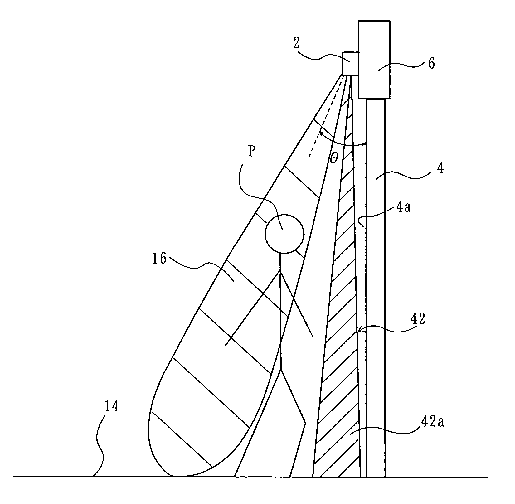
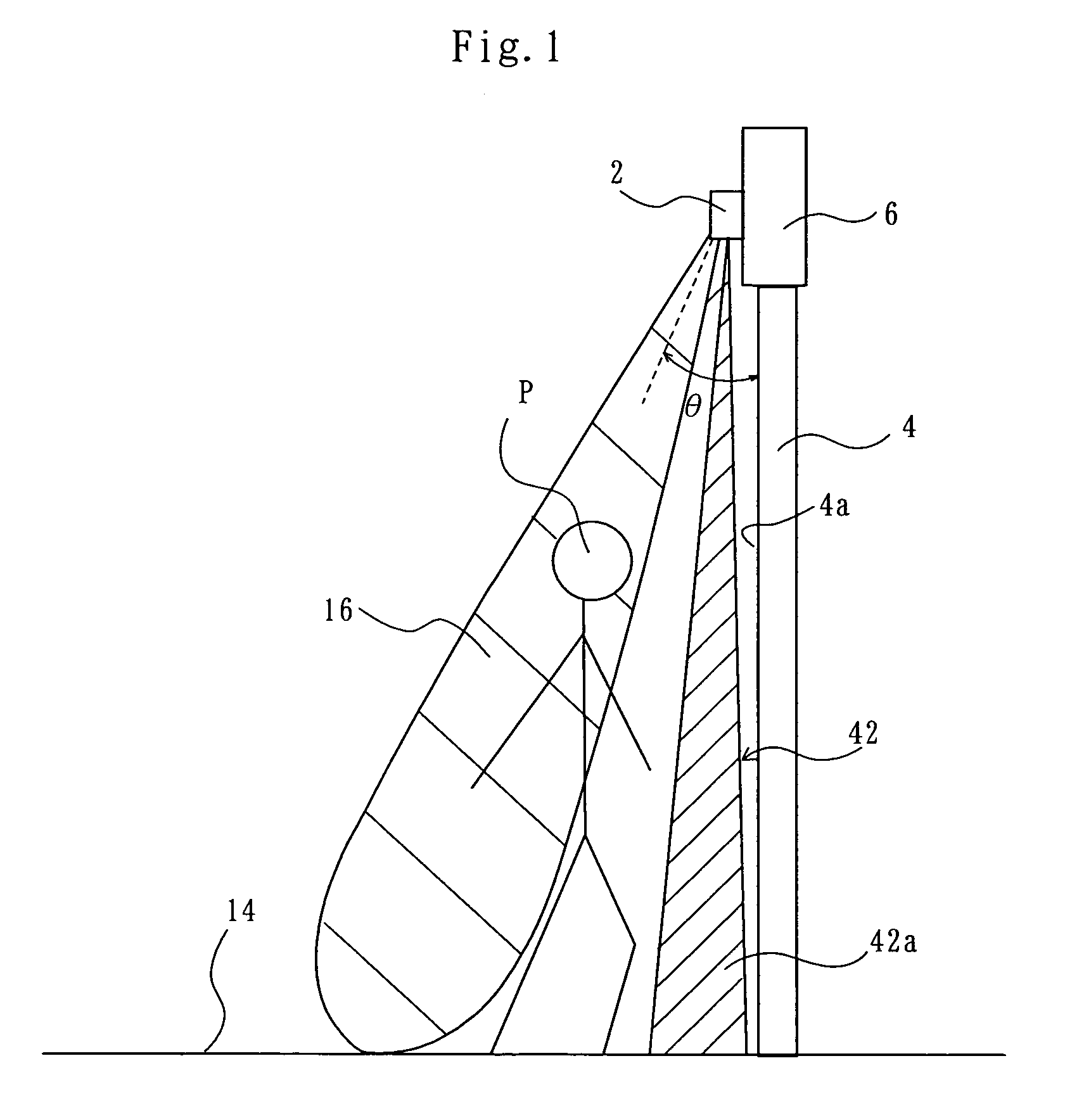
[0041]As shown in FIG. 1, a composite sensor 2 according to the present invention is installed on a lintel 6 above an automatic door 4. The door 4 shown in FIG. 1 is a double sliding door as shown in FIG. 2, which includes two door panels pulled open and closed away from and toward each other.

[0042]As shown in FIG. 4, the composite sensor 2 has a radio-wave transmitting-receiving module 8, in which a radio-wave transmitter-receiver section 12 (FIG. 5) is housed. The radio-wave transmitter-receiver section 12 transmits a radio wave, e.g. a microwave, from an antenna 10 and receives a reflected microwave to detect a moving object, e.g. a pedestrian. The module 8 is disposed to send and receive a radio wave toward and from a floor 14 as shown in FIG. 1. The transmission and reception of the radio wave produces a radio-wave detection zone 16 extending from the module 8 to the floor 14. The shape of the radio-wave detection zone 16 is dependent on the directivity pattern of the antenna 1...

second embodiment

[0067]As shown in FIG. 12, door position detecting means for sensing whether the door 4 is in its closed position is used in association with the CPU 50. The door position detecting means may be a limit switch 60, for example. The limit switch 60 is disposed in the lintel 6. The limit switch 60 is turned ON when the door 4 is in the closed position, and otherwise is turned OFF. The CPU 50 monitors the limit switch 60 as to find whether it is ON or OFF. As shown in FIG. 13, if the switch 60 is ON, the result of detection in the safeguard zone 42 is invalidated. In other words, when the limit switch 60 is ON, a safeguard zone signal, i.e. a received-light representative signal, inputted to the CPU 50 from the light emitter-receiver section 20 is ignored, and it is treated as if there is no pedestrian in the safeguard zone 42. On the other hand, when the limit switch 60 is OFF, the result of detection in the safeguard zone 42 is made valid and is reflected in the sensor output.

[0068]T...

third embodiment

[0081]The CPU 50 of the third embodiment operates to validate the result of detection in the safeguard zone 42 only when an object or pedestrian is detected in the activation zone 16, and otherwise invalidate the result of detection in the safeguard zone 42.

[0082]For that purpose, the CPU 50 operates to execute the safeguard zone evaluation processing, along the procedure as illustrated by a flow chart shown in FIG. 17. First, the CPU 50 makes a judgment, in Step S31, as to whether an object has been detected in the activation zone 16. This judgment is made based on the result of detection obtained in Step S3 shown in FIG. 14.

[0083]If it is judged, in Step S31, that an object has been detected, the CPU 50 advances to Step S33, where it validates the result of detection in the safeguard zone 42, and ends the safeguard zone evaluation processing of FIG. 17. On the other hand, if no object has been detected in activation zone 16, the CPU 50 advances from Step S31 to Step S35 and invali...


PUM


Abstract

A radio-wave transmitter-receiver section (12) forms a radio-wave detection zone (16) for detecting an object at a location way from a door (4). A light emitter-receiver section (20) forms an optical detection zone (42) for detecting an object at a location along and closer to the door (4). The light emitter-receiver section (20) includes mirrors (28, 36) which are used to increase or decrease the depth dimension of the optical detection zone (42) in the direction perpendicular to the door (4).

Description

[0001]The present invention relates to a door sensor which detects an object in the vicinity of, for example, an automatic door, and more particularly to a composite door sensor including sensors for detecting an object by means of radio waves and light.BACKGROUND OF THE INVENTION[0002]An example of such composite door sensor is disclosed in a catalog of B.E.A. Inc., entitled “ACTIV8.3”, retrieved through the Internet at the B.E.A. Inc. website on Jan. 29, 2003.[0003]The composite sensor disclosed in this catalog includes a microwave transmitter-receiver section and an infrared (IR) emitter-receiver section in a single casing. A microwave is used to detect a moving object, e.g. pedestrian, moving toward a door. When a pedestrian is detected by the microwave transmitter-receiver section, the door is opened. IR light is used to detect an object, e.g. a pedestrian, standing stationary in the vicinity of the door. When the pedestrian is detected by the IR emitter-receiver section, the d...

Claims


Application Information

Patent Timeline
Patent Type & Authority Patents(United States)
IPC IPC(8): G08B13/08G01S13/04G01S13/86G01S17/04G01S17/86
CPCG01S13/04G01S13/86G01S17/023E05F15/43G01S17/026E05Y2900/132E05F2015/765E05F15/73E05F2015/434E05F2015/487G01S17/04G01S17/86
Inventor SASAKI, SHIGEAKINISHIGAKI, KENJIKANDA, YASUTAKA
Owner NABCO LTD
Why Eureka
Try Eureka