Image forming system and device, and control method and control program for controlling image forming device

Active Publication Date: 2006-06-20
MINOLTA CO LTD
View PDF2 Cites 23 Cited by
  • Summary
  • Abstract
  • Description
  • Claims
  • Application Information

AI Technical Summary

Benefits of technology

[0011]This invention improves the power saving control for the image forming device. This invention can reduce the consumption of the image forming device without seriously affecting the efficiency of printing work. If the distance between the image forming device and the portable terminal does not change after a predetermined length of time has passed, the power

Problems solved by technology

In this conventional control technology, however, the image forming device cannot start printing immediately when the user operates or gives a printing instruction, if the image forming device is in the power saving mode, until the

Method used


Image

  • Image forming system and device, and control method and control program for controlling image forming device
  • Image forming system and device, and control method and control program for controlling image forming device
  • Image forming system and device, and control method and control program for controlling image forming device

Examples


embodiment 1

(Embodiment 1)

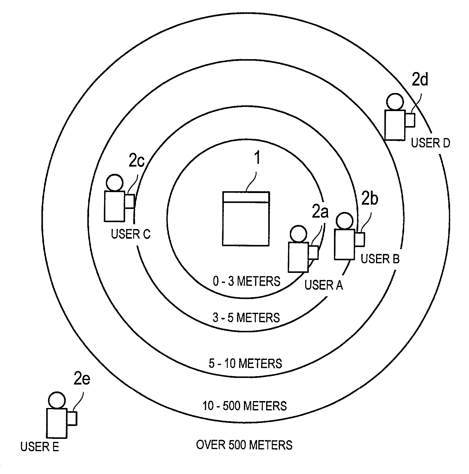
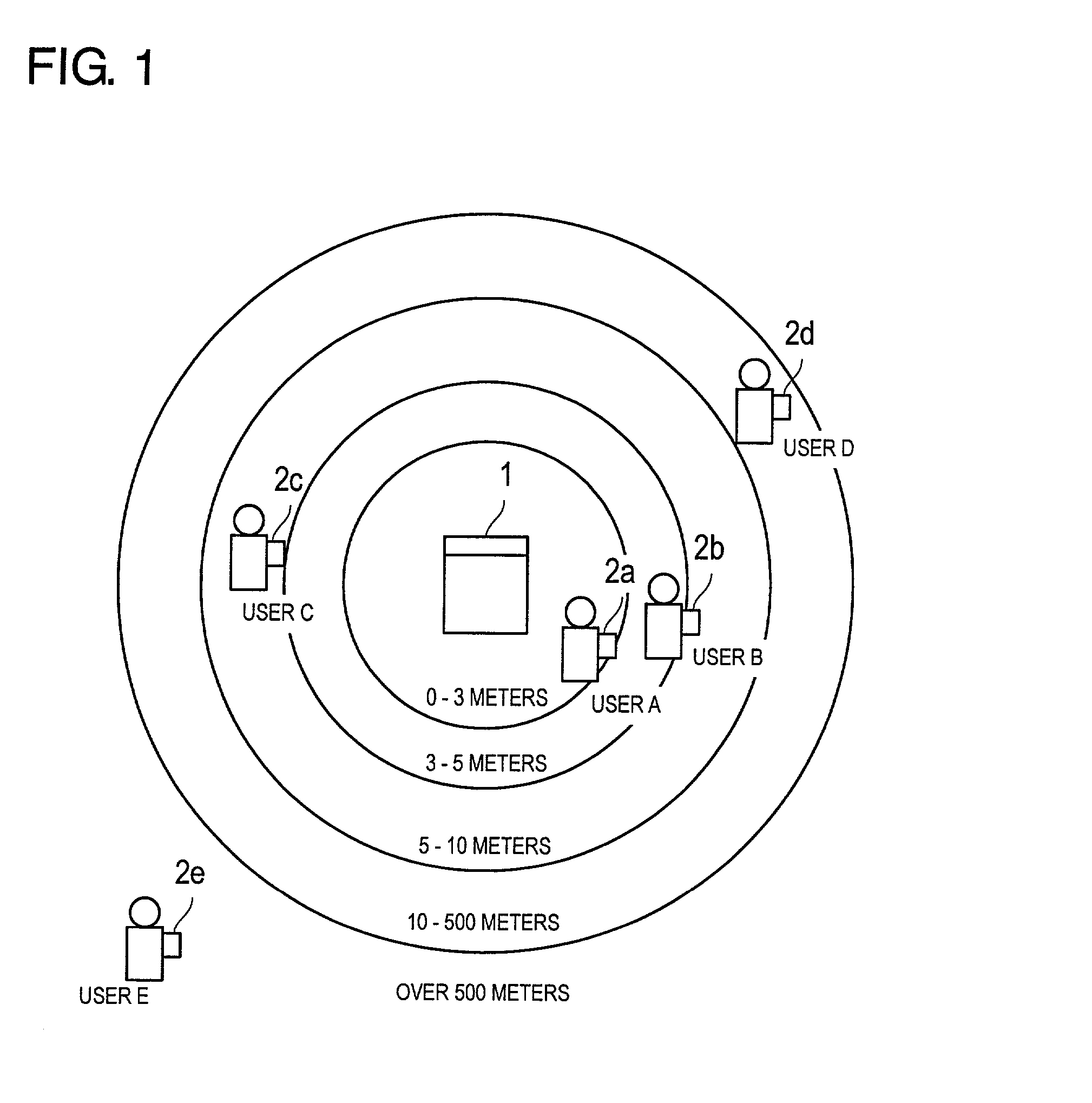
[0031]In the first embodiment, a case is described where the present invention is applied to an image forming system having a digital copying machine. In the present embodiment, temperature control is performed for a fusing unit in accordance with the distance between the portable terminal and the digital copying machine as one type of power saving control.

[0032]FIG. 1 is an example of the operating condition of a digital copying machine 1. The digital copying machine 1 is capable of wireless communication with multiple portable terminals 2a through 2e. A reference number 2 denotes an arbitrary terminal. The portable terminal 2 performs function of transmitting the identification information and informing the location of itself. The portable terminal 2 is a digital communication medium such as a PHS® (Personal Handy-phone System), a cellular phone, or a PDA. The portable terminal 2 wirelessly transmits data such as voice and telephone numbers as digital signals as radi...

embodiment 2

(Embodiment 2)

[0073]The second embodiment is a case where the present invention is applied to an image forming system having a computer and a printer. In this embodiment, when the user carrying a portable terminal approaches the computer, the power saving control is performed in accordance with the distance between the computer and the portable terminal.

[0074]FIG. 10 is a diagram showing the operating condition of the system having a computer 5 and a printer 7.

[0075]The computer 5 is capable of wirelessly communicating with portable terminals 6a through 6b. A reference number 6 in the following description denotes an arbitrary portable terminal. The function of the portable terminal 6 will not be described here, as it is essentially the same as the function of the portable terminal 2 described in the first embodiment.

[0076]As shown in FIG. 10, the user A has a portable terminal 6a and the user B has a portable terminal 6b. The portable terminal 6a of the user A is registered in the ...


PUM


Abstract

The image forming system includes a digital copying machine 1 and portable terminals 2. The digital copying machine 1 has a wireless communication unit 40, which is wirelessly communication with the portable terminals 2. The digital copying machine 1 identifies a portable terminal located closest to the digital copying machine 1 out of multiple portable terminals 2 that are in communicable conditions. As the distance between the identified portable terminal 2 and the digital copying machine 1 reduces, the temperature of heating rollers 31 is controlled to rise.

Description

[0001]This application is based on Japanese Patent Application No. 2001-4087 filed on Jan. 11, 2001, the contents of which are hereby incorporated by reference.BACKGROUND OF THE INVENTION[0002]1. Field of the Invention[0003]The present invention relates to a system comprising a portable terminal and an image forming device, in particular, to power saving technology for the image forming device. The present invention further relates to a system comprising an image forming device, a portable terminal and a control device for controlling the image forming device.[0004]2. Description of Related Art[0005]Concerning digital copying machines, printers and other image forming devices, a control technology is known for automatically switching the image forming device to power saving mode in order to reduce power consumption during the standby period when printing process and other operations are not performed for some time. For example, the control technology is applied to an image forming d...

Claims


Application Information

Patent Timeline
IPC IPC(8): G06F3/12G03G21/00G03G15/00G03G15/20H04N1/00
CPCG03G15/2003G03G15/5004H04N1/00H04N1/00928H04N1/00323H04N1/00912H04N1/00127
Inventor IDEHARA, TAKENORI
Owner MINOLTA CO LTD
Why Eureka
Try Eureka